smartIO 8x24 SCPI
Set di comandi SCPI per smartIO 8x24
Utilizzo generale
The help could be called in several ways:
 '__?'       => Print all commands
 '__? ?'     => Print the list of all sections
 'can:__?'   => Print the 'can' section help
 '__? can'   => Other way to print the 'can' section help
 '__? sta'   => Print commands starting with 'sta'

The commands can be entered in the short form (shown in capital letters in the help)
or in the long form. Intermediate lengths are not permitted.
The commands can be specified in uppercase or lowercase letters.
Parameters are separated with commas.
Several commands in one line are separated with ';'.
Comments start with '//'.
General Commands
__?                 Print this help                             __?
*IDN?               Prints an identifying string. The response  *idn?
                    will show the following information:
                    <company name>, <model nr>, <serial nr>, <firmware rev>
*SAVe               <par> Save parameters                       *sav 0
*LOAd               <par> Load parameters                       *load 0
                          par = 0: Flash
                                f: set to defaults
                                a: ALL to def. including serial NR...
*REPeat             <period> Repeat the command line periodic.   adc:val? 0; *rep 1000
                    Command is added to another command with ';'.
                    It could be placed anywhere in the line.
                    It repeats the commands with the given period [ms]
                    Range 10 - 10000ms
                    The periodic repetition is ended by pressing any key
*INLine             [sep] Print all following answers in one   *inl;*rep 1000;adc:val? 0;adc:val? 4
                    line separated by TAB. This is useful in
                    combination with the *repeat command.
                    Optional the separator characters could
                    be given as parameter. Example             *inl \tHallo\n
                    Special Strings: \n, \r, \t,
                    \s = space, \c = ',', \. = ';'
System Commands
SYStem:LEDbright attenua ora soltanto l'heartbeat in idle (funzionamento normale/admin); il boot (autotest +
versione del firmware) e la segnalazione degli errori vengono eseguiti sempre alla massima luminosità1.
SYStem:__?          Print System Help                           system:__?
SYStem:ERRor?       Output last error
SYStem:SERial       Set serial number                           system:serial 1800390000
                    Structure: YYPPPPNNNNN
                          YY = production Year
                          PPPP = Product code (0062)
                          NNNNN = serial Number
SYStem:SERial?      Output serial number                        system:serial?
SYStem:PROd         Set production date                         system:prod 20240630
SYStem:PROd?        Output production date                      system:prod?
SYStem:COMment      Save comment to device                      system:comment Hello World
SYStem:COMment?     Output comment                              system:comment?
SYStem:VARiant      Set the variant of the module               system:variant +-60V
SYStem:VARiant?     Output variant                              system:variant?
SYStem:DEBug        Set debug level                             system:debug 0
                    0 = Off, 1, 2, 3
SYStem:DEBug?       Output debug level                          system:debug?
SYStem:COLor        <enable> Enable/Disable colored messages    system:color 1
SYStem:COLor?       Query colored messages                      system:color?
SYStem:UFLock       <enable>,<pwd> Enable/Disable flashing      system:uflock 1,123456
                      over ext USB by persistently locking RTS/DTR control lines
                      <pwd> as uint32 is assigned with setting the lock (0: keep prev).
SYStem:UFLock?      Query USB Flash Lock Status                 system:uflock?
SYStem:LEDbright    <bri> LED brightness (0..255)               system:led 100
                      Only dims the idle heartbeat (normal/admin operation).
                      Boot (self-test + firmware-version) and error display
                      always run at full brightness (255).
SYStem:LEDbright?   Query LED brightness                        system:led?
SYStem:BITlen       <ms> Status LED blink code base bit length  system:bitlen 250
                      All other blink-code timings (bit, preamble, separator,
                      sync-pause) are fixed multiples of this base unit.
SYStem:BITlen?      Query status LED blink code base bit length system:bitlen?
SYStem:INFo?        Query information                           system:info?
SYStem:TEMp?        Query internal temperature [Deg C]          system:temp?
SYStem:SWVer?       Query software version and compile date     system:swver?
                      Also replays the version number on the status LED
                      (blue preamble + major/minor blink code, same as at boot)
SYStem:HWVer?       Query hardware version (r=raw)              system:hwver?
SYStem:SCPiinfo?    Query SCPI information                      system:scpiinfo?
SYStem:CPUload?     Query CPU load                              system:cpuload?
SYStem:SLEep        <cpu>,<ms> Debug let CPU to sleep           system:sleep 0,100
                      CPU0: ADC read, CAN
                      CPU1: SCPI, LED, Display,...
SYStem:REStart      Restart the smartIO                         system:restart
SYStem:DATetime?    Print the internal date/time                system:dat?
SYStem:DATetime     Set the internal date/time (yyyy.mm.dd)     system:dat 2024.05.26 12:07:12
                    It's possible to set the date only:         system:dat 2024.05.27
                    Date and time is used in the log files...
SYStem:TIMe         Set the internal time only                  system:time 12:07:12
SYStem:UTC          Set CAN-ID receiving UTC timestamps         system:utc 0x010
                      0: disable, rxData{uint48_Motorola, 0, crc}

SYStem:UTC?         Query CAN-ID receiving UTC timestamps       system:utc?
SYStem:ALL_ids?     Query all CAN message IDs                   system:all?
SYStem:ADMin        <enable>,<pwd> Enable/Disable admin mode    system:admin 0,123456
                      <pwd> as uint32 is assigned with disabling (0: keep prev)
SYStem:ADMin?       Query admin mode enabled                    system:admin?
SYStem:SHA          Test sha256 algorithm                       system:sha <text>
SYStem:ECHo         Test scpi parser, echo input                system:echo <param>,...
Status LED1
Il LED singolo a pixel WS2812 mostra la sequenza di boot, lo stato idle e le classi di errore come sequenze di colori.
Il tempo di bit di base è impostabile tramite system:bitlen (default 250 ms); tutti gli altri tempi
(separatori, pause) sono multipli fissi di questo valore. L'autotest subito dopo l'accensione è l'unica
eccezione e viene eseguito sempre con tempo fisso, indipendentemente da system:bitlen.
Sequenza dopo l'accensione:
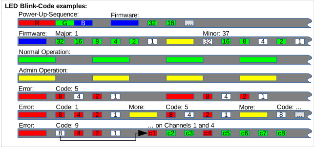
- Autotest: rosso – verde – blu, 200 ms ciascuno, senza pausa tra l'uno e l'altro.
- Pausa (3× il tempo di bit di base).
- Annuncio della versione del firmware (ripetibile tramite
system:swver?): blu (preambolo, 3×) → versione principale (6 bit, MSB first, bianco = 1 / verde = 0, 1× il tempo di bit di base per ogni bit incl. fase finale) → giallo (separatore, 3×) → versione decimale (6 bit, stesso schema) → pausa (4×, sync). - Successivamente heartbeat in idle.
Heartbeat in idle: 1 volta al secondo verde per un breve istante, altrimenti spento. Finché system:admin è attivo, al posto del verde viene utilizzato il giallo (promemoria visibile che la modalità admin è attiva).
Segnalazione degli errori (sostituisce l'heartbeat in idle finché è attiva almeno una classe di errore): rosso (preambolo, 3×) → per ogni classe di errore attiva un codice a 4 bit (bianco = 1 / rosso = 0, MSB first); per le classi relative ai canali segue una pausa (3×) e successivamente una bitmap dei canali a 8 bit (rosso = 1 / canale interessato, verde = 0 / canale ok), canale 0 per primo, canale 7 per ultimo. Tra più codici attivi si trova un separatore giallo (3×); segue una pausa di sync (4×), poi si torna al preambolo (se gli errori sono ancora attivi) oppure all'heartbeat in idle.
| Codice | Significato | Tipo |
|---|---|---|
| 1 | Errore CAN | globale |
| 2 | ADC bloccato (interrupt DR da ~3s senza nuovi dati) | globale |
| 3 | Reset watchdog rilevato (una sola volta, solo subito dopo il boot) | globale |
| 4 | Errore CRC del registro di configurazione MCP3914 (adc:crc?) | globale |
| 5 | Reset da panic rilevato (stack overflow, corruzione dell'heap, eccezione, ...), una sola volta, solo subito dopo il boot1 | globale |
| 8 | Overrange | per canale |
| 9 | Errore CMT (Common-Mode-Trim mancante/fuori campo, calib:cmstat?) | per canale |
| 10 | Calibrazione mancante nel gain/nella modalità attivi | per canale |
I codici 1-5 e 8/9/10 corrispondono 1:1 ai bit nell'item CAN 8120 (codici 1-5) ovvero alle bitmap dei canali negli item CAN 8100 (Overrange), 8101 (errore CMT) e 8102 (errore No-CAL) -- vedere CAN Mapping.
I reset da watchdog e da panic (codici 3/5) scrivono inoltre immediatamente al boot una voce nel
registro eventi (file:log)1 -- in quanto uniche classi di errore rare ma critiche che sono rilevabili solo dopo
il riavvio. Errori CAN, overrange ed errori CMT/CAL restano intenzionalmente solo telemetria
LED/CAN, senza voce nel registro eventi.
Diagrammi temporali per le sequenze più importanti (sequenza di power-up, versione firmware 1.37, funzionamento normale e admin in idle, un singolo codice di errore, più codici di errore globali simultanei, nonché un codice relativo ai canali su canali selezionati):
Analog Digital Converter Commands
I comandi MCP3914-STATUSCOM (ADC:REAd/WRIte/DRHiz/DRLink/CWIdth/WIDth/ECRc/EINt,
ciascuno con la variante di query ?) sono nuovi1.
idx = Channel index: 0...7
      'all': all channels (default if omitted)
ADC:__?             Print ADC Help                              adc:__?
ADC:VALue?          <idx> [,dec] Query value of a channel       adc:value? 3,4
                          idx = Channel-index (all:print all)
                          dec = Optional decimal places (default 3)
ADC:RAW_value?      <idx> Query raw value of channel            adc:raw_value? all
                          idx = Channel-index (all:print all)
ADC:BIN_value?      <idx> Query binary value of channel         adc:bin_value? all
                    Data are filtered with EMA (see below)
ADC:HEX_value?      <idx> Query hexadecimal value of channel    adc:hex_value? all
                    Data are filtered with EMA (see below)
ADC:DEVbits?        <idx> [,Rst] Query Bits needed to code      adc:devbits? all, 1
                    the deviation of the channel
                          Rst = 1 Restart calculation (default)
                                0 Accumulate calculation
ADC:LOSt?           Query lost AD data                          adc:lost?
ADC:SPEed?          Query ADC Speed [1/second]                  adc:speed?
ADC:CRC?            Query cached MCP3914 config-register CRC    adc:crc?
                          0x0000 = not yet established (unlocked / just (re)locked)
ADC:SLOw            <enable> Read AD-Data slow (Debug)          adc:slow 0
                          enable = 1: Data are only read when printed.
                                      Fast CAN Messages are not sent
                                      Filters and statistics are not calculated
                                   0: Using maximal data rate (Standard)
ADC:SLOw?           Query Read AD-Data slow (Debug)             adc:slow?
ADC:TAU             <Tau> for Exponential Moving Average        adc:tau 0.5
                    filter (EMA, 1st order low pass)
                          Tau [s] (Default:0 = Disabled)
ADC:TAU?            Query Tau for Exponential Moving Average f. adc:tau?
ADC:CURrent         <idx>,<enable> Current mode enable         adc:current 3,1
                          idx    = Channel-index (all:set all)
                          enable = 0: Voltage mode
                                 = 1: Current mode
ADC:CURrent?        <idx> Query Current mode                   adc:current? all
ADC:FILt            <idx>,<enable> Sallen Key Low Pass filter  adc:filt 3,1
ADC:FILt?           <idx> Query Sallen Key Low Pass filter     adc:filt? all

ADC:UNIt            <idx>,<unit> Set Unit for the channel      adc:unit 1, V
                           unit = V/mA ('-': Automatic switch V/mA)
ADC:UNIt?           <idx> Query Unit for the channel           adc:unit? 8
ADC:POLynom         <idx>,<coef[]> Set polynom for sensor      adc:polynom 1, -2.88, 3.24, -0.35
                           up to 15 coefficients in descending power of x
                           0 := empty polynom, which bypasses x
                           Example: -2.88 x^2 + 3.24 x - 0.35
ADC:POLynom?        <idx> Query polynom for the channel        adc:polynom? 8
ADC:MCLk            <mclk> Master Clock frequency [MHz]        adc:mclk 4
                          mclk = 0.1..10 [MHz] (Default 4 MHz)
ADC:MCLk?           Query Master Clock frequency [MHz]         adc:mclk?
ADC:QENable         <enable> ADC quartz oscillator             adc:qenable 1
ADC:QENable?        Query ADC quartz oscillator enable         adc:qenable?
ADC:DELay           <del> Power up Delay [ms]                  adc:delay 50
                    Time between power up and reset of the ADC
ADC:DELay?          Query Power up Delay [ms]                  adc:delay?
ADC:POWer           <enable> Analog Power                      adc:power 0
                          enable = 0 (off), 1 (on), 2 (immediate reset cycle:
                          full power off/on, does not persist as "2" -- readback
                          settles back to 1)
ADC:POWer?          Query Analog Power                         adc:power?
MCP3914 PGA Gain Configuration Register (see 8.5 on page 63)
ADC:GAIn            <idx>,<gain> Programmable Gain Amplifier   adc:gain 0,8
                          idx = Channel-index (all:set all)
                          gain = 1, 2, 8, 16 or 32
ADC:GAIn?           <idx> Query PGA gain                       adc:gain? 0
                          idx = all: print all gains
ADC:REGister        <reg>, <val> Write AD-converter register   adc:reg 0x0B, 0
                    ! ONLY for EXPERTS !
                    The example sets the Gain register to 0.
                    => All gains = 1, Attention: The rest of
                    the SW dosn't know this => AD-Values show
                    'val' could be given in Hex, Bin (0B) or decimal
                    The registers are NOT stored permanently.
ADC:REGister?       <reg> Query AD-converter register          adc:reg 0x0B, 0
                          reg = all: All registers
                                cha: analog channels
                                inp: Important registers

MCP3914 STATUSCOM Register: (See 8.6 on page 64)
Die Setter-Kommandos erfordern aktivierten Admin-Modus (system:admin), sonst ExecutionNotPermitted.
ADC:REAd            <mode> Address Counter Increment Setting   adc:read 2
                    for Read Communication.
                          mode = 3  ctr auto-increments entire register map
                                 2  ctr auto-increments on register TYPES (default)
                                 1  ctr auto-increments on register GROUPS
                                 0  ctr not incremented
ADC:REAd?           Query Address Counter Increment Setting    adc:read?
                    for Read Communication.
ADC:WRIte           <enable> Address Counter Increment         adc:write 1
                    Setting for Write Communication
ADC:WRIte?          Query Address Counter Increment            adc:write?
                    Setting for Write Communication
ADC:DRHiz           <enable> Data Ready Pin Inactive State     adc:drhiz 0
                          enable = 1  DR pin is logic high when data are NOT ready
                                   0  DR pin is high-impedance (default)
ADC:DRHiz?          Query Data Ready Pin Inactive State        adc:drhiz?
ADC:DRLink          <enable> Data Ready Link Control bit       adc:drlink 1
                          enable = 1  Data ready link enabled;
                                      one pulse generated for all ADC channels
                                   0  Data ready link disabled;
                                      each ADC produces its own pulse
ADC:DRLink?         Query Data Ready Link Control bit          adc:drlink?
ADC:CWIdth          <enable> CRC-16 Format on Communications   adc:cwidth 0
                          enable = 1  32-bit (CRC-16 code is followed by sixteen zeros)
                                   0  16 bit (default)
ADC:CWIdth?         Query CRC-16 Format on Communications      adc:cwidth?
ADC:WIDth           <mode> ADC Data Width Format Settings      adc:width 1
                          mode = 3  32-bit with sign extension (Test only)
                                 2  32-bit with zeros padding  (Test only)
                                 1  24-bit
                                 0  16-bit with rounding (default)
ADC:WIDth?          Query ADC Data Width Format Settings       adc:width?
ADC:ECRc            <enable> CRC-16 Checksum on Serial         adc:ecrc 0
                    Communications
                          enable = 1  CRC-16 checksum is provided at the end of
                                      each communication sequence
                                   0  Disabled (default)
ADC:ECRc?           Query CRC-16 Checksum on Serial com.       adc:ecrc?
ADC:EINt            <enable>  CRCREG Interrupt Enable bit      adc:eint 0
                          enable = 1  Interrupt flag for the CRCREG checksum enabled.
                                   0  Disabled (default)
ADC:EINt?           Query CRCREG Interrupt Enable bit          adc:eint?

MCP3914 CONFIG0 Register (see 8.7 on page 66)
ADC:DITher          <dith> Dithering Circuit for Idle Tone’s   adc:dither 3
                    Cancellation and improved THD on all channels
                          dith = 3 Strength = Maximum (default)
                                 2 Strength = Medium
                                 1 Strength = Minimum
                                 0 Dithering turned off
ADC:DITher?         Query Dithering                            adc:dither?
ADC:BOOst           <bias> Bias Current Selection for all ADCs adc:boost 1
                    (=Ruhestrom)
                          bias = 2    current x 2 (default)
                                 1    current x 1
                                 0.66 current x 0.66
                                 0.5  current x 0.5
ADC:BOOst?          Query Bias Current                         adc:boost?
ADC:PREscale        <pre> Prescale Analog Master Clock         adc:Prescale 1
                          pre =  8  AMCLK = MCLK/8
                                 4  AMCLK = MCLK/4
                                 2  AMCLK = MCLK/2
                                 1  AMCLK = MCLK/1 (default)
ADC:PREscale?       Query Prescale Analog Master Clock         adc:Prescale?
ADC:OSR             <osr> Oversampling Ratio for Delta-Sigma   adc:osr 256
                    A/D Conversion (All Channels)
                          osr = 4096 (default), 2048, 1024,
                                 512, 256, 128, 64, 32
ADC:OSR?            Query Oversampling Ratio                   adc:osr?
ADC:VREfcal         <cal> Internal Voltage Temperature         adc:vrefcal 80
                    Coefficient (See 5.6.3 on page 35
ADC:VREfcal?        Query Internal Voltage Temperature         adc:vrefcal?
                    Coefficient (See 5.6.3 on page 35
Statistic informations for ADC data
STAtistic:__?       Print Statistic Help                        sta:__?
STAtistic:STDdev?   <idx> Query Standard Deviation              sta:stddev? all
STAtistic:RMS?      <idx> Query Root Mean Square                sta:rms? all
STAtistic:AVG?      <idx> Query arithmetic average              sta:avg? all
STAtistic:ARRay?    <idx> Query Statistic array elements        sta:array? all
STAtistic:CLR       <idx> clear statistics array                sta:clr all
STAtistic:SIZe      Set Statistic array size (all channnels)    sta:size 500
STAtistic:SIZe?     <idx> Query Statistic size (all channnels)  sta:size? all
                    Returns the filled array elements. If the ADC interrupt
                    is enabled this is equal to the defined elements.
Calibration interface for ADC
CALib:CMStat? è nuovo1.
Description of the calibration interface for ADC modules
idx = Channel index: 0...7
      'all': all channels (default if omitted)
CALib:__?           Print Calibration Help                      calib:__?
CALib:AUTo          <idx>,<point>,<value> n-point               calib:auto all,0,0.0
                    calibration of the channel via the          calib:auto all,1,10.0
                    value:
                          idx = channel index
                          point = calibration point 0 (start) or any other >0
                          value = calibration value in V or mA
                    If the Exponential Moving Average filter is
                    enabled (Tau > 0) the filtered values are
                    used for the calibration. => Wait until the
                     values are stable before starting the command.
CALib:FACtory       <idx>,<passwd> reset calibration            calib:factory 0,<passwd>
                    of a channel to factory settings
                           idx    = channel index
                           passwd = 0x########, ASCI codes of 'clrF'
CALib:SCAle         <idx>,<value> Set scale factor              calib:scale 0,1.245
                    of a channel (related to 24-bit full scale):
                           idx = channel index
                    <value> = Scale factor [double]
CALib:SCAle?        <idx> [,gain] Query the scale factor of     calib:scale? 0
                    a channel (related to 24-bit full scale)    Return: 1.5666346371E-06
                           idx = channel index
                           gain = optional gain (1,2,..32, all)
CALib:OFFset        <idx>,<value> Set offset of a channel       adc:offset 0,-200.1
                          idx = channel index
                          value = offset [double]
CALib:OFFset?       <idx> [,gain] Query offset of a channel     calib:offset? 0
                          idx = channel index                   Return: -3.3971688151E-01
                          gain = optional gain (1,2,..32, all)
CALib:CMTrim        <idx>, <val> Common Mode Trimmer            calib:cmtrim 0, 121
                          <val> is uint8 or control command of
                            start : take calibration         @ V_CM = 0.0 V
                            step  : one step of compensation @ V_CM = 100 V
                            break : abort trimming process
                            status: display trimming status
                          A list of CMTrim, measured ADC and status is returned
CALib:CMTrim?       <idx> Query Common Mode Trimmer             calib:cmtrim? 0
CALib:CMStat?       Query CMT-missing channel bitmask (bit per  calib:cmstat?
                    channel, set when the channel's last calib:cmtrim sweep
                    ended in a range error -- read-only, no setter)
Description of the CAN interface
CAN:__?             Print CAN Help                              can:__?
CAN:BAUd            <baud> Define CAN Bus baud rate             can:baud 500
CAN:BAUd?           Query CAN Bus baud rate                     can:baud?
CAN:FACtory         <passwd> Preset CAN Messages to             can:factory <passwd>
                      factory defaults:
                          ID     ms     content
                          0x0F0, 30000, 9000, 9001, 9002
                          0x0F1,    10,    0,    1
                          0x0F2,    10,    2,    3
                          0x0F3,    10,    4,    5
                          0x0F4,    10,    6,    7
                          0x0F5,   100,  200,  201
                          0x0F6,   100,  202,  203
                          0x0F7,   100,  204,  205
                          0x0F8,   100,  206,  207
                          0x0FD,  1000, 8000, 8001, 8002, 8300, 8301, 8110
                          passwd = 0x########, ASCI codes of 'clrF'
CAN:MSG             Define CAN Messages                         can:msg 0x123, 1000, 0, 1
                      Parameters: MsgId, Period, DataTyp1, DataTyp2,..
                          MsgId = Message ID 11 or 29 bit (Hex or decimal)
                          Period = send period (< 2^24 ms)
                                   Special periods:
                                   0: Sent as RTR only
                                  -1: Sent at program start
                                  -2: Sent at program start and as RTR
                          DataTypX = Defines the data types.
                      Print detailed help with                  can:msg ?
CAN:MSG?            <MsgId> Queries the CAN message             can:msg? all
CAN:DELmsg          <MsgId> Delete the CAN message              can:delmsg all
CAN:FILter          <MsgId>, <Rtr> Test CAN Filter              can:filter 0x123,0
                          MsgId = calc:  Calculate the filter   can:filter calc
                                  all:   Pass all messages (Disable Filter)
CAN:TBOot           <msDelay> Info Msg Time delay after boot   can:tboot 60000
CAN:TBOot?          Query Info Msg Time delay after boot       can:tboot?
CAN:NBOot           <number> Info Msg number of repeats        can:nboot 3
CAN:NBOot?          Query Info Msg number of repeats           can:nboot?
CAN:TINfo           <msDelay> Info Msg Repeat interval time    can:tinfo 500
CAN:TINfo?          Query Info Msg Repeat interval time        can:tinfo?
CAN:DBGmode         <mode> bit-mask for debug messages         can:dbgmode 255
CAN:DBGmode?        Query bit-mask for debug messages          can:dbgmode?
Display Commands
DISplay:__?         Print Display Help                          display:__?
DISplay:TYPe        <disp> Set the display type                 display:typ 13
                          disp: 13 = 1.3  inch OLED
                                96 = 0.96 inch OLED

DISplay:TYPe?       Query the display type                      display:typ?
DISplay:ROTation    <rot> Set the display rotation              display:rot 2
                          rot: 0 = normal orientation
                               1 = rotate by 90  deg
                               2 = rotate by 180 deg
                               3 = rotate by 270 deg
DISplay:ROTation?   Query the display rotation                  display:rot?
File handling commands
FILe:__?            Print File Help                             file:__?
FILe:DIR            List files [Filter]                         file:dir *.txt
FILe:DEL            <name> Delete the given file                file:del test.txt
FILe:CAT            <name> Print the given file                 file:cat test.txt
FILe:HEX            <name> Print the given file as hex dump     file:hex test.dat
FILe:GET            <name> get file as base64 encoded           file:get test.bin
FILe:PUT            <name> put file as base64 encoded           file:put test.bin <base64>
FILe:LOG            Print the log file                          file:log
ISO-TP+ terminal and administrative interface
Parameters to use the SCPI protocol over CAN
Each SmartIO could be configured with individual CAN messages
ISOtp:__?           Print ISO-TP+                               iso:__?
ISOtp:TRA_id        ISO-TP+ transmit message ID                 iso:tra 0x06200005
                       0: disabled, reserved for future use
ISOtp:TRA_id?       Query ISO-TP+ transmit message ID           iso:tra?
ISOtp:REC_id        ISO-TP+ receive message ID                  iso:rec 0x06200006
                       0: disabled, reserved for future use
ISOtp:REC_id?       Query ISO-TP+ receive message ID            iso:rec?

ISOtp:ADMin:TRA_id  Admin ISO-TP+ transmit message ID           iso:adm:tra 0x012
                       channel from smartIO to smiocan-app
ISOtp:ADMin:TRA_id? Query Admin ISO-TP+ transmit message ID     iso:adm:tra?
ISOtp:ADMin:REC_id  Admin ISO-TP+ receive message ID            iso:adm:rec 0x011
                       channel from smiocan-app to smartIO
ISOtp:ADMin:REC_id? Query Admin ISO-TP+ receive message ID      iso:adm:rec?
ISOtp:ADMin:BRKms   <ms> ISO-TP+ break between CF               iso:adm:brk 5
ISOtp:ADMin:BRKms?  Query ISO-TP+ break between CF              iso:adm:brk?
ISOtp:ADMin:PKSize  <bytes> ISO-TP+ packet size to FC           iso:adm:pks 128
ISOtp:ADMin:PKSize? Query Admin ISO-TP+ packet size to FC       iso:adm:pks?
ISOtp:ALL_ids?      Query all message IDs                       iso:all?
ISOtp:FILter        Assign filter rules for ISO-TP+ messages    iso:filter 'get', '!=0(1)'
                       for internal use only
Software Update over CAN
Debug functions for the CAN update
UPDate:__?          Print Software Update Help                  upd:__?
UPDate:INFo?        Print infos                                 upd:info?
UPDate:SWAppart     Swap the active partition                   upd:swappart
                    Restart the system afterwards to be applied
UPDate:FMT          Format the unused partition                 upd:fmt
UPDate:VALid        Mark the current partition valid indicate   upd:valid
                    that the running app is working well.
UPDate:INValid      Mark the current partition invalid and      upd:invalid
                    roll back to the previously workable app
                    with reboot
UPDate:BEGin        <size>, [<seed>] start receiving FW-Image   upd:begin 123456
                    until <size> bytes received. Each BLOB is of type 'fwImg'
                    and up to 4k bytes.
UPDate:END          <sha256>, <mode> validate received image    upd:end B7639AB..., auto
                    by comparing the sha256 checksum. If image is validated:
                    <mode>: auto   activate new firmware and restart
                          : flash  flash the image only, do not acitvate
                          : activ  flash & activate the image, do not restart
                    other modes: ignored.