smartDrive
Description
The smartDrive is a rugged, Linux-based quad-core edge computing device for demanding mobile and stationary applications, e.g. in rail, commercial vehicles, construction and agricultural machinery, or industrial plants. It combines a powerful application processor with cellular (LTE), GNSS, WLAN/Bluetooth, and extensive CAN, serial, digital, and analog interfaces in an IP67-protected housing.
The device runs optiMEAS Yocto Linux with smartCore. This allows the smartDrive to be fully connected to optiCLOUD.
Key features:
- Quad-core application processor at 1.6 GHz, optional NPU (up to 2.3 TOPS) and GPU
- optiMEAS Yocto Linux with smartCore, fully connectable to optiCLOUD
- LTE Cat4 with UMTS/GSM fallback, GNSS receiver (GPS/GLONASS/Galileo/BeiDou), optional WLAN/Bluetooth
- 4x CAN interfaces (optionally usable as CAN-FD), 12 configurable digital I/Os, 4 analog inputs, RS232/RS485
- Programmable 3-axis accelerometer, optional gyroscope
- Housing protection class IP67 / IP6K9K, operating temperature -40 °C to +75 °C
- Optional security features: High Assurance Boot (HAB) and TPM 2.0
optiMEAS reserves the right to make changes and is not liable for errors regarding this and all further data, descriptions, or examples provided for this product.
Hardware
Processor and memory
| Parameter | Remark |
|---|---|
| Application processor | Quad-core Cortex-A53, 64 bit, 1.6 GHz, additional Cortex-M7 (low-power domain) |
| NPU | optional, up to 2.3 TOPS |
| GPU | optional, OpenVG 1.1, G2D, OpenGL® ES 3.1, Vulkan®, OpenCL™ 1.2 FP |
| RAM | 2 GB LPDDR4 (optional up to 4 GB) |
| Flash (eMMC) | 8 GB (optional up to 32 GB) |
| Flash (NAND) | 1 GB SLC |
| Removable storage | microSD |
| Storage available to user | approx. 950 MB RAM; approx. 5.1 GB (8 GB eMMC) or 13.5 GB (16 GB eMMC), approx. 800 MB NAND flash |
| Operating system | optiMEAS Yocto Linux with smartCore, fully connectable to optiCLOUD |
| Security | HAB (High Assurance Boot); optional TPM 2.0 (ISO/IEC 11889) |
Cellular (LTE / UMTS / GSM)
| Parameter | Remark |
|---|---|
| Technology | LTE Cat4 with UMTS/HSPA+ and GSM/GPRS/EDGE fallback |
| LTE-FDD | B1/B2/B3/B4/B5/B7/B8/B12/B13/B18/B19/B20/B25/B26/B28 |
| LTE-TDD | B38/B39/B40/B41 |
| UMTS | B1/B2/B4/B5/B6/B8/B19 |
| GSM | 850/900/1800/1900 MHz |
| Data rate LTE-FDD | max. 150 Mbit/s (DL), max. 50 Mbit/s (UL) |
| Data rate LTE-TDD | max. 130 Mbit/s (DL), max. 30 Mbit/s (UL) |
| Data rate UMTS | DC-HSDPA max. 42 Mbit/s (DL), HSUPA max. 5.76 Mbit/s (UL) |
| GPRS | Multislot class 33 |
| Transmit power | 2.5 W (GSM850/EGSM900), 1.8 W (GSM1800/1900), 2.1 W (WCDMA), 2.8 W (LTE) |
| SIM | integrated mini-SIM holder (flip type), 3 V. Only regular mini-SIM cards must be used, not micro-/nano-SIM cards cut down to size. |
GNSS
| Parameter | Remark |
|---|---|
| Receiver | 72-channel, concurrent reception of GPS, GLONASS, QZSS, BeiDou, Galileo E1B/C |
| SBAS | WAAS, EGNOS, MSAS, GAGAN |
| Update rate | up to 10 Hz (5 Hz with concurrent reception of multiple satellite systems) |
| Accuracy | 2 m CEP |
| Signal acquisition | cold start 26 s, warm start < 1.5 s |
| Datum | WGS-84 |
| Sensitivity | tracking/reacquisition -167 dBm, cold start -148 dBm |
| Active antenna supply | +3.0 V @ 30 mA, with short-circuit and open-circuit detection |
Sensors
The smartDrive features a programmable 3-axis accelerometer (measuring range ±2 g/±4 g/±8 g/±16 g), which also serves as a wake-up source from standby/off. An optional 3-axis gyroscope (±125/±250/±500/±1000/±2000 dps) with a data rate of up to 416 Hz is additionally available.
An internal temperature sensor measures the housing's internal temperature in the range -40 °C to +75 °C (accuracy ±5 °C). It is not suitable for measuring ambient temperature.
The system time is provided by the CPU system clock as well as a battery-backed RTC (backup duration 10 years). When leaving OFF/STANDBY, the CPU system time is automatically taken over from the RTC.
Power supply and battery backup
| Parameter | Remark |
|---|---|
| Supply voltage | 9 to 36 V DC (nominal voltage 24 V) |
| Reverse polarity / overvoltage protection | yes, at the voltage input |
| External fusing | 20 A (to be provided externally by the user) |
| Current draw @ 24 V, RUN | 51.95 mA |
| Current draw @ 24 V, RUN + GSM in call + Ethernet | 145 mA |
| Current draw @ 24 V, STANDBY | 14.20 mA |
| Current draw @ 24 V, OFF | 0.67 mA |
| RTC/GNSS backup battery | fixed installation, non-rechargeable, backup duration 10 years |
The device has the operating states No Power, OFF, STANDBY, and RUN. From OFF and STANDBY, the device can be brought back to the RUN state via configurable events (motion, digital inputs, RS232 reception, CAN-FD, Ethernet, Bluetooth, GSM).
Housing and mechanics
| Parameter | Remark |
|---|---|
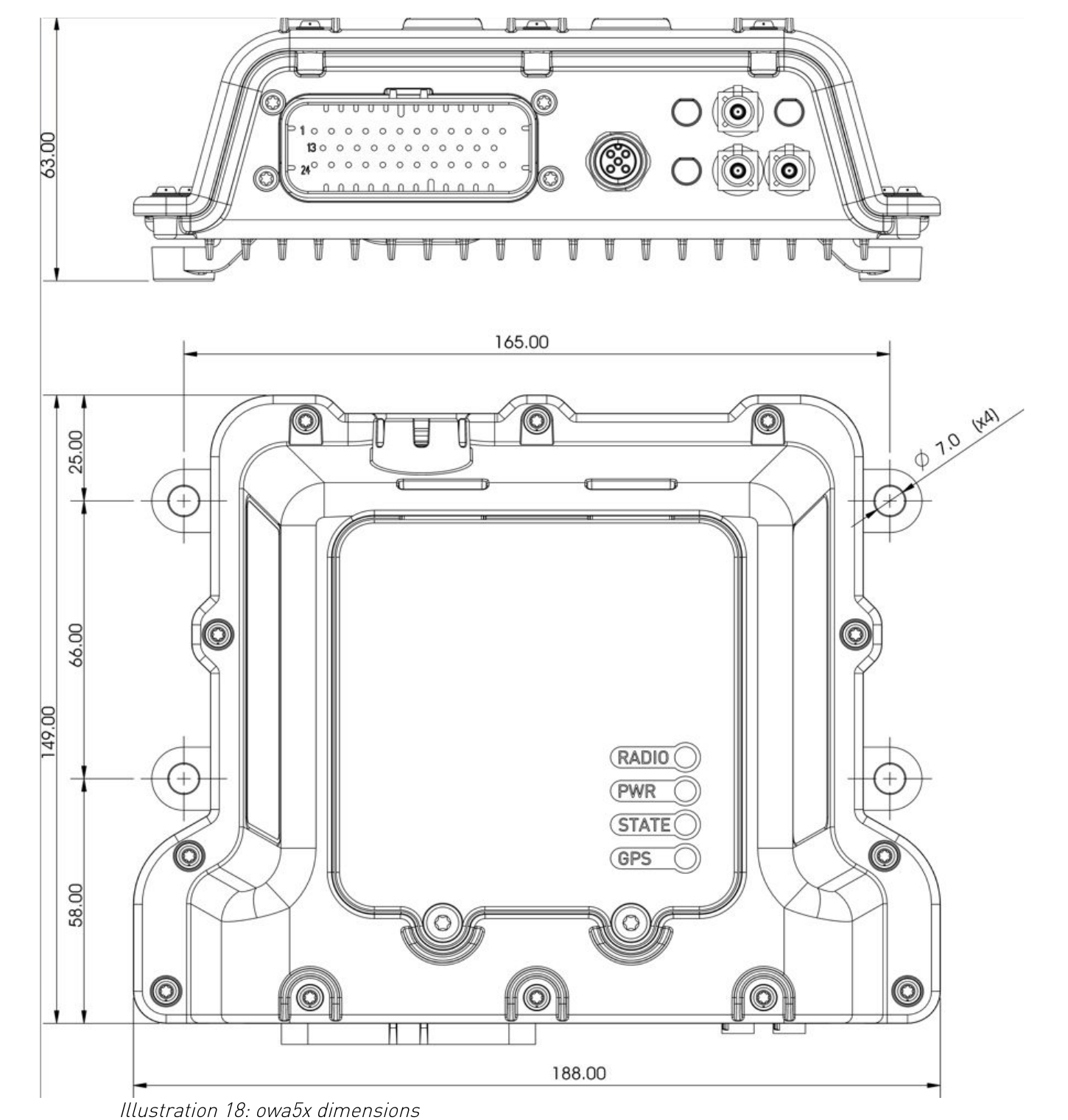
| Dimensions (W x L x H) | 188 x 149 x 63 mm |
| Mounting hole pattern | 165 x 66 mm, 4 x Ø 7 mm (M4) |
| Weight | 699 g ± 5 g (without backup battery), 878 g ± 5 g (with backup battery) |
| Material | glass-fiber reinforced plastic, anodized aluminum |
| Protection class | IP67 / IP6K9K (protection against dust and water) |
| Operating temperature | -40 °C to +75 °C (GSM off), -30 °C to +75 °C (GSM on); with optional Li-Ion battery: -20 °C to +60 °C (battery operation), 0 °C to +45 °C (charging) |
| Storage temperature | -40 °C to +85 °C |
| Mounting | any orientation, 4 mounting holes at the housing ends |
Connector interfaces
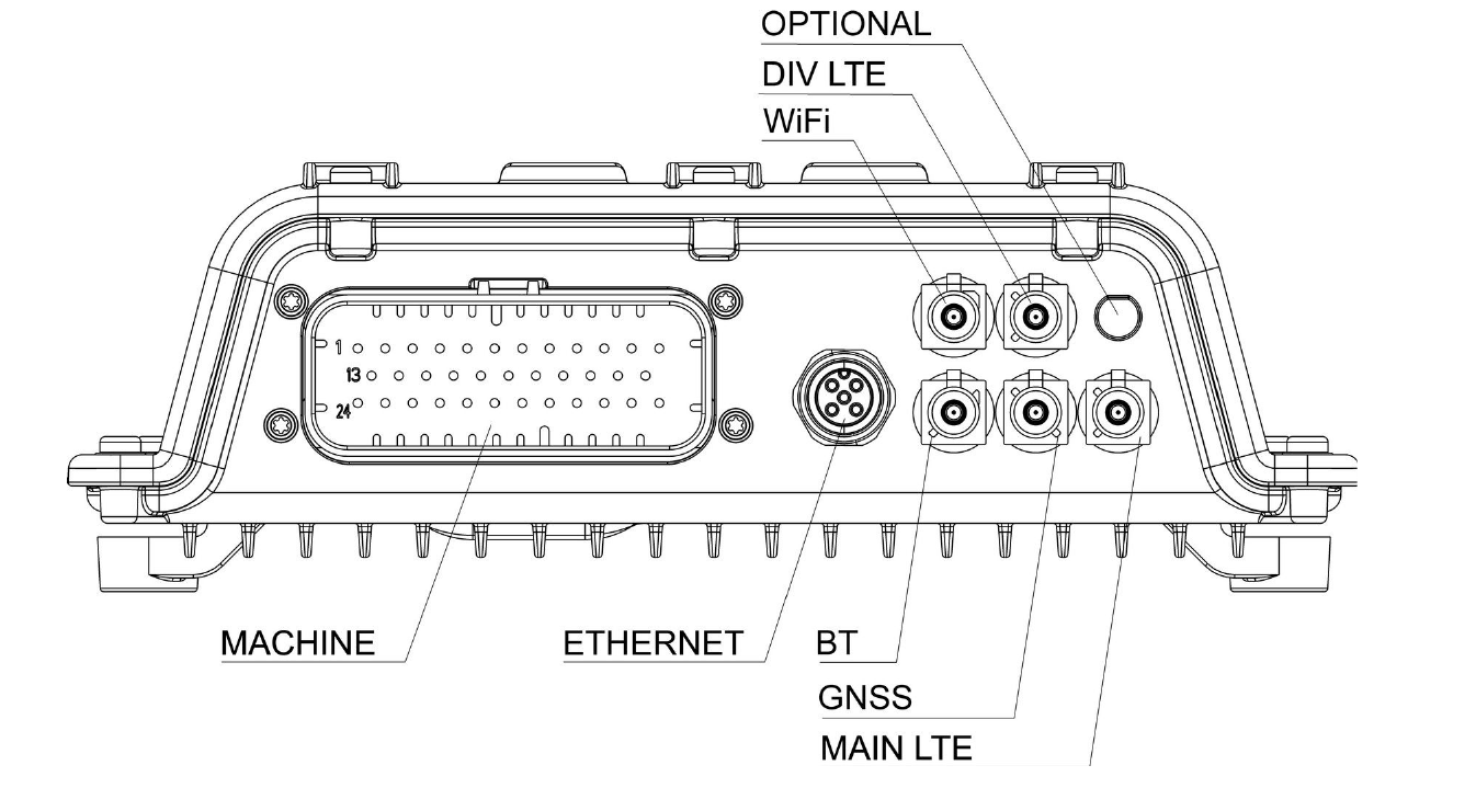
All external connectors are located on the front of the housing. The Bluetooth and WLAN antennas are installed internally and do not require an external connector.
| Designation | Connector |
|---|---|
| MACHINE | 35-pin main connector (power supply, CAN, digital/analog I/Os, serial) |
| ETHERNET | M12 D-coded (100BASE-T1 or 100BASE-TX, optional) |
| MAIN LTE / DIV LTE (optional) | FAKRA, cellular antenna connector |
| GNSS | FAKRA, GNSS antenna connector |
| BT / WiFi (optional) | FAKRA or internal antenna |
"MACHINE" main connector (35-pin)
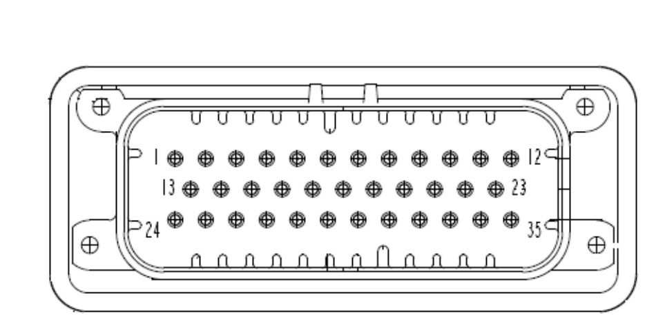
The main connector provides the power supply, 4 CAN (optionally CAN-FD) and RS232 interfaces, as well as digital and analog I/Os.
| Connector | Type |
|---|---|
| Receptacle on device | TE 776164-1 (35-pin) |
| Mating connector | TE 776164-1 |
| Crimp contacts | TE 770520-1 |
| Pin | Signal | Type / Function |
|---|---|---|
| 1 | V_OUT (5V) | Voltage output, 4.5–5.2 V, max. 900 mA |
| 2 | ON/OFF | Input: leave open = ON, switch to GND = OFF |
| 3 | AIN2 | Analog input |
| 4 | AIN3 | Analog input |
| 5 | CANH1 | CAN bus 1, high |
| 6 | CANL1 | CAN bus 1, low |
| 7 | CANH2 | CAN bus 2, high |
| 8 | CANL2 | CAN bus 2, low |
| 9 | CAN1 TERM | 120 Ω termination resistor for CAN bus 1 |
| 10 | CAN2 TERM | 120 Ω termination resistor for CAN bus 2 |
| 11 | CANH4 | CAN bus 4, high |
| 12 | CANL4 | CAN bus 4, low |
| 13 | GND | Ground |
| 14 | GND | Ground |
| 15 | AIN0 | Analog input |
| 16 | DIO-0 | digital I/O (input/output) |
| 17 | DIO-1 / AIN1 | digital I/O or analog input (multiplexed) |
| 18 | DIO-2 / CAN3L | digital I/O or CAN bus 3, low |
| 19 | DIO-3 / CAN3H | digital I/O or CAN bus 3, high |
| 20 | DIO-4 | digital I/O (input/output) |
| 21 | DIO-5 | digital I/O (input/output) |
| 22 | DIO-6 / iButton | digital I/O or 1-Wire iButton bus (multiplexed) |
| 23 | DIO-7 | digital I/O (input/output) |
| 24 | V_IN | Power supply, 9–36 V DC |
| 25 | DIO-8 (high-side) | digital output, high-side, max. 1 A |
| 26 | DIO-9 (high-side) | digital output, high-side, max. 1 A |
| 27 | TXD-1 | RS232, transmit line |
| 28 | RXD-1 | RS232, receive line |
| 29 | RTS-1 | RS232, handshake |
| 30 | CTS-1 | RS232, handshake |
| 31 | TXD-2 / RS485A | RS232, transmit line, or RS485-A (factory option) |
| 32 | RXD-2 / RS485B | RS232, receive line, or RS485-B (factory option) |
| 33 | DIO-10 | digital I/O (input/output) |
| 34 | DIO-11 | digital I/O (input/output) |
| 35 | CAN4 TERM | 120 Ω termination resistor for CAN bus 4 |
Some pins have multiple assignments (multiplexing) and cannot be used simultaneously: AIN1/DIO-1, DIO-2/DIO-3 with CAN3, DIO-6/iButton, as well as DIO-1 with RS485 on UART2 (RXD-2/TXD-2). The active function is configured in software.
Power supply
| Pin | Signal | Min | Max |
|---|---|---|---|
| 24 | V_IN | 9 V | 36 V |
| 13 / 14 | GND | – | – |
| 2 | ON/OFF | OFF: 0–0.5 V | ON: leave open |
The supply line is protected against reverse polarity and overvoltage; external fusing of 20 A must be provided. The V_OUT output (pin 1) provides up to 900 mA at 5 V, e.g. for powering connected sensors.
Digital inputs/outputs (DIO0 – DIO11)
All 12 digital channels can be individually configured as input or output and are not TTL-compatible; they tolerate input voltages up to 50 V.
| Property | Remark |
|---|---|
| Input impedance | 180 kΩ (DIO-0: 220 kΩ, DIO-6: 1 kΩ pull-up to +5 V) |
| Output DIO0–DIO7, DIO10, DIO11 | Open-collector/open-drain, up to 50 V, max. 200 mA (low-side) |
| Output DIO8, DIO9 | High-side switch against V_IN, max. 1 A |
| Wake-up function | any input can be configured as a wake-up source from standby/OFF |
| Counter function | any input can be used as a 32-bit counter (odometer) up to 3 kHz |
For inductive loads (e.g. relays) on the outputs, a freewheeling diode must be provided to limit the switch-off voltage spike.
Analog inputs (AIN0 – AIN3)
| Parameter | Remark |
|---|---|
| Resolution | 12 bit |
| Measuring range | 0–5.12 V (5 mV/bit) or 0–30.72 V (30 mV/bit), switchable in software |
| Accuracy | ±1 % typ. at 25 °C |
| Input impedance | 110 kΩ (AIN1: 68 kΩ) |
CAN bus
| Parameter | Remark |
|---|---|
| Number | 4x CAN, optionally usable as CAN-FD per bus |
| Bit rate | 1 Mbit/s (arbitration), 2 Mbit/s (data phase); optionally CAN3/CAN4 with 5 Mbit/s data phase |
| Termination resistor | internally switchable (120 Ω) via CANx_TERM pins, to be connected to the CANL of the respective bus |
Ethernet (M12 D-coded, optional)
The optional M12 D-coded Ethernet is available either as Single Pair Ethernet (100BASE-T1) or as classic 10/100BASE-TX.
| Pin | Signal (100BASE-T1) | Signal (100BASE-TX) |
|---|---|---|
| 1 | TRX-P | TX+ |
| 2 | – | RX+ |
| 3 | TRX-N | TX- |
| 4 | – | RX- |
| Connector | Type |
|---|---|
| Receptacle on device | M12, D-coded, 4-pin, female |
| Mating connector | M12, D-coded, male |
When using the 100BASE-T1 variant, a media converter to 100BASE-TX is required to connect to standard Ethernet.
USB 3.0 Type A
The USB connector (top side) supports mass storage devices.
| Pin | Signal | Function |
|---|---|---|
| 1 | VBUS | +5 V |
| 2 | D- | Data - |
| 3 | D+ | Data + |
| 4 | GND | Ground |
| 5 | StdA_SSRX- | SuperSpeed receiver - |
| 6 | StdA_SSRX+ | SuperSpeed receiver + |
| 7 | GND DRAIN | Signal ground |
| 8 | StdA_SSTX- | SuperSpeed transmitter - |
| 9 | StdA_SSTX+ | SuperSpeed transmitter + |
Connector: USB Type A, mating connector Type A (male), max. current load 900 mA.
Antenna connectors
| Connector | Connector type | Remark |
|---|---|---|
| MAIN LTE / DIV LTE (optional) | FAKRA, male, coding D (Bordeaux) | Impedance 50 Ω |
| GNSS | FAKRA, male, coding C (blue) | Impedance 50 Ω, active antenna required (+3.0 V @ 30 mA, recommended gain 15 dB, 1575.42 MHz, VSWR max. 2.0:1) |
| WiFi / Bluetooth (optional) | internal | no external antenna required |
Only sealed FAKRA connectors must be used to maintain the IP67 protection of the antenna connections.
Card slots and status LEDs (top side)
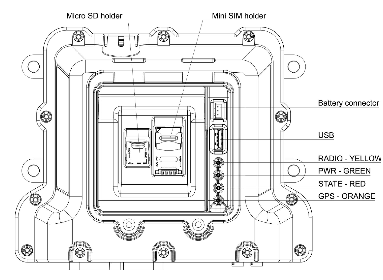
Under a screwed-on, transparent cover (2 screws, Torx T20, tightening torque 1.3 Nm) are the mini-SIM and microSD card holders as well as the internal battery connector for the optional backup battery.
| Holder | Type | Remark |
|---|---|---|
| Mini-SIM | flip-type holder | 3 V and 1.8 V SIM cards |
| microSD | flip-type holder | additional storage |
Four status LEDs on the top side indicate the operating state:
| LED | Color | Meaning |
|---|---|---|
| RADIO | yellow | lights up when an internet connection is active, regardless of whether it is established via the cellular modem or via Ethernet/network |
| PWR | green | lights up when the device is powered on |
| STATE | red | blinks at 1 Hz as long as the smartCore process is running without errors; if the LED does not blink, an error is present |
| GPS | orange | lights up continuously when a valid GPS signal is received; requires a GPS module entered in the smartCore configuration |
Technical data (summary)
| Parameter | Value |
|---|---|
| Processor | Quad-core Cortex-A53, 1.6 GHz |
| RAM | 2 GB LPDDR4 (up to 4 GB) |
| eMMC | 8 GB (up to 32 GB) |
| Supply voltage | 9–36 V DC |
| Protection class | IP67 / IP6K9K |
| Dimensions (W x L x H) | 188 x 149 x 63 mm |
| Weight | 699 g / 878 g (with backup battery) |
| Operating temperature | -40 °C to +75 °C (GSM off) / -30 °C to +75 °C (GSM on) |
| Storage temperature | -40 °C to +85 °C |
| Cellular | LTE Cat4, UMTS, GSM/GPRS/EDGE |
| GNSS | GPS, GLONASS, BeiDou, Galileo, QZSS |
| CAN | 4x CAN (optionally CAN-FD) |
| Digital I/Os | 12x configurable |
| Analog inputs | 4x, 12 bit |
| Serial | 2x RS232 (2nd port optionally RS485) |
| Ethernet | optional, M12 D-coded, 100BASE-T1 / 100BASE-TX |
| USB | 1x USB 3.0 Type A |
| Main connector | 35-pin, TE 776164-1 |