smartIO Configuration
Parameterization is carried out via the integrated USB interface, behind which a serial/UART chip
serial/UART chip enables serial communication with the controller. The
protocol is SCPI.
The configuration interface is used, for example, to set calibration parameters and assign
identifiers are assigned for the CAN messages.
Connection
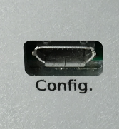
In order for the module to be parameterized, it must be connected to the PC via the micro-USB socket. PC via the micro USB socket. The configuration software used is the free optiMEAS optiControl is used as configuration software.
Automatic search
After the software has been started, a
device search is performed and all modules found are displayed in the device list:
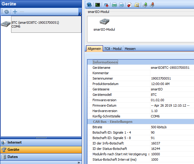
*Device list with smartIO module
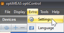
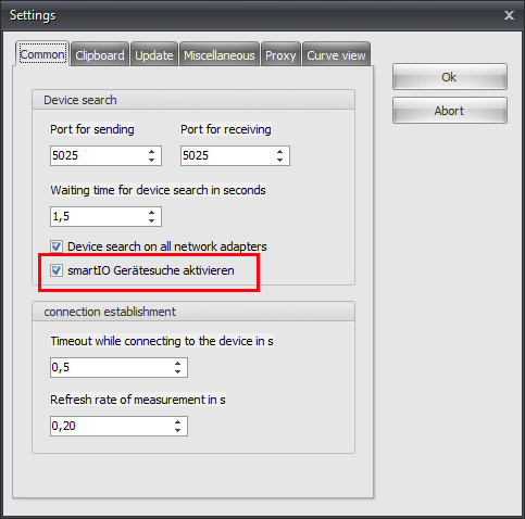
In order for a module to be found automatically by the software, the option
"Activate smartIO device search" under "Extras -> Settings" must be activated. This
causes the optiControl software to scan all serial ports (USB) for smartIO modules.
modules.
Manual search
On some devices, the automatic search is not available due to security settings.
If you are using such a device, deactivate the automatic device search under "Extras -> Settings" (see automatic search).
A green "plus" symbol now appears in the header of the device list.
Click on it to open a pop-up in which you can select a COM port to which optiCONTROL should connect.
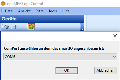
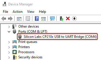
If several COM ports are available for selection, you can determine the correct COM port in the device manager of your device. To do this, search for "Silicon Labs CP210x USB to UART Bridge" under the "Ports (COM & LPT)" category and select the specified COM port in optiCONTROL.
If the module is still not recognized, make sure that the Silicon Labs CP210x drivers are installed on your device.
You can find the drivers on the Silicon Labs website.
Configuration
The desired device can now be selected to read and display the current settings.
and display them. In the individual tab areas and in the toolbar, all available functions are
available to adjust parameters and write them to the module.
module.
![]()
| Icon | Description |
|---|---|
| Read module settings | |
| Show SCPI console. | |
| Write or save current settings to the module. Must always be carried out after changing the configuration. | |
| Export the current information and parameters as an Excel or CSV file, e.g. for documentation purposes. | |
| Export the current settings of the CAN messages as a DBC file. | |
| Export the current settings of the CAN messages as text in DBC format. Can be copied from the popup. | |
| Export the module settings as an SCPI file. | |
| Import module settings from an SCPI file. |
General area
The general area displays information about the module, such as the serial number, firmware date, hardware and firmware version and offers the option of change basic parameters.
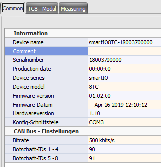
The following parameters can be adjusted and saved in this area:
- Comment
- Bit rate (baud rate) of the CAN bus interface
- The IDs for the 2 CAN messages sent by the module.

So that changed parameters are persistently written to the module,
the save button ![]() must always be clicked after an adjustment!
must always be clicked after an adjustment!
Measure area
In the measurement area, all or individual sensor inputs can be selected and the current
current measured values can be displayed. To do this, simply check the box in front of the desired signal
and press the start button ![]() .
.
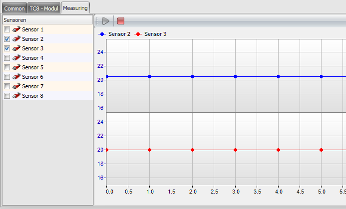
The measurement data is always displayed in this preview function at approx. 1 Hz, regardless of which sampling rate is set in the general range. This value only applies to the CAN bus, not for this display!
Module-specific parameters
The following chapters describe the module-specific setting parameters of the various smartIOs. various smartIOs are described.
The IDs of the CAN messages must be unique for the entire CAN network so that data is not corrupted. If you use several smartIO devices in a CAN network, make sure that the standard IDs are unique.
TC8
The specific setting parameters of the TC8 module are set in the "TC8 - Module" tab. tab.
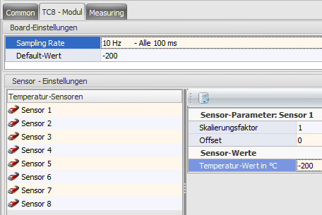
Board settings
The general module parameters are displayed under Board settings and can also be can also be changed there. The following parameters can be adjusted there be adjusted there:
| Parameter | Description |
|---|---|
| Sampling rate | Specifies the time interval at which the data is sent via the CAN bus interface. |
| Default value | This value is sent as a substitute value as soon as no thermocouple is connected to the signal input. The default value is -200. |
Sensor settings
The scaling factors, offsets and current sensor values can be displayed under Sensor settings.
The displayed sensor value can be refreshed by clicking on the refresh button ![]() .
.
The parameters of the sensors are based on the calibration of the device and cannot be changed here. If you want to use a different scaling or offset for a conversion to a different unit of measurement (e.g. V to bar), you can set this in the DBC configuration on the counter device.
8U12 and 8I12
The specific setting parameters of the 8U12 / 8I12 module are set in the tab "8U12 - Module" or "8I12 - Module" tab.
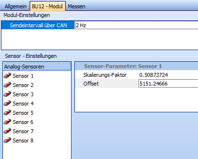
The transmission interval of the measurement data on the CAN bus can be set under Board settings. The scaling factors and offsets of each analog sensor can also be displayed.
The parameters of the sensors are based on the calibration of the device and cannot be changed here. If you want to use a different scaling or offset for a conversion to a different unit of measurement (e.g. V to bar), you can set this in the DBC configuration on the counter device.
MIO1
The specific setting parameters of the MIO1 module are set in the "MIO1 - Module" tab.
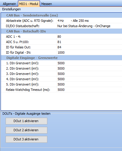
CAN bus - transmission intervals
The transmission intervals of various CAN bus messages can be displayed and changed under "CAN bus - Transmission intervals". The following parameters can be adjusted there:
| Parameter | Description |
|---|---|
| Sampling rate (ADC and RTD signals) | Specifies the time interval at which the measurement data from the analog sensors is sent via the CAN bus interface. |
| DI/DO status message | Specifies the time interval at which the status of the digital inputs and outputs are sent via the CAN bus interface. OnChange" can also be selected here, whereby the status message is only sent when the status of an input or output changes. |
CAN Bus - Message IDs
The IDs for the various CAN messages sent by the module can be displayed and changed under "CAN Bus - Message IDs". The messages are divided as follows:
| Message | Description |
|---|---|
| ADC 1 - 4 | The ID of the CAN message that contains the measurement data of the first four analog sensors. |
| ADC 5 and Pt100 | The ID of the CAN message containing the measurement data of the fifth analog sensor and the measurement data of the Pt100 sensor. |
| ID for Relay Out | The ID of the CAN message containing the status message of the digital outputs. |
| ID for Digital - IN | The ID of the CAN message containing the status message of the digital inputs. |
Digital inputs - limit values
The limit or threshold values of the digital inputs and outputs can be displayed and changed under "Digital inputs - limit values".
| Parameters | Description |
|---|---|
| The minimum voltage in mV above which the corresponding analog input is to be interpreted as "on". | |
| Relay watchdog timeout (ms) | The maximum time in ms for which the relays of the digital outputs may be active. If a relay exceeds this limit, it is automatically switched off. |
DOUTs - Test digital outputs
The "DOUTs - Test digital outputs" section can be found under the settings.
The digital outputs of the module can be activated here with a click in order to test the electrical connection during commissioning.
8X24
The 8X24 can be parameterized more granularly than any other smartIO module to date. Due to this granularity, the settings of the 8X24 are divided into three subcategories: Input Settings, CAN Message Settings and Module Info.
Input Settings
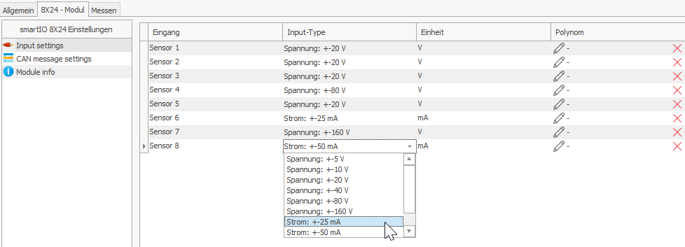
The settings for the analog sensors of the 8X24 can be found in the Input Settings. The quantity and range to be measured from voltage and current can be selected here for each sensor. A polynomial can also be set up that is used to convert a voltage or current measurement directly on the module into another physical unit.
Polynomial (sensor scaling)

Another coefficient can be added to the polynomial by clicking the + button in the top left-hand corner of the pop-up.
Pressing the X button removes the currently selected coefficient.
In the "User-defined unit" field, you can enter any physical unit that is expressed by this polynomial.
CAN message settings
With all previous smartIO modules, only the IDs of the CAN messages can be edited. In contrast, the 8X24 allows you to define your own CAN messages. This is done in the CAN message settings.
When setting up CAN message IDs, please note that these must be unique throughout the entire CAN network. Duplicate IDs can lead to data loss.
At the top of the section you will find a range of tools for configuring CAN messages.
| Icon | Description |
|---|---|
| Apply default or minimum settings. Are immediately written to the device. | |
| Add new CAN message. | |
| Remove selected CAN message. | |
| Export current configuration as a file. | |
| Import configuration from file. |
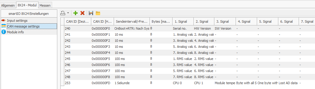
The CAN messages to be produced by the 8X24 are listed in a table below the toolbar.
The following fields can be customized for each CAN message:
| Field | Description |
|---|---|
| CAN ID [Decimal] | The ID of the CAN message in decimal. Entries are automatically displayed in hexadecimal in the next field. |
| CAN ID [Hexadecimal] | The ID of the CAN message in hexadecimal. Entries are automatically displayed in decimal in the previous field. |
| Transmission interval/frequency | How often the corresponding CAN message should be sent. |
| Bytes (read-only) | Automatically calculated number of bytes that the CAN message contains. A CAN message may contain a maximum of 8 bytes. This is a restriction of the CAN protocol (Wikipedia). |
| 1st - 8th signal | Which signals/measured values are to be transmitted in the message. Note the length of the signals in bytes. |
Invalid entries in the CAN ID fields are discarded without a message and the last valid value continues to be used.
In contrast to the other smartIO modules, the 8X24 sends CAN messages in Motorola format (Big Endian).
This special feature is reflected in the DBC files generated by optiCONTROL, but must be taken into account for manual configurations.
Signals
The 8X24 produces a large number of signals that can be assigned to CAN messages.
To assign a signal to a CAN message, click on one of the eight signal slots and select the desired signal in the pop-up.
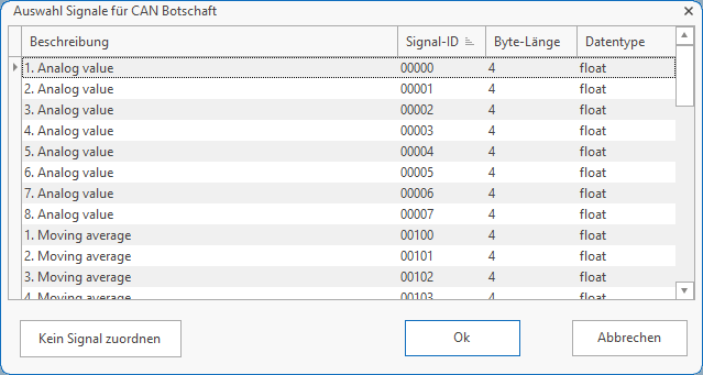
To remove a signal from a CAN message, open the configuration of the signal and click the "Do not assign signal" button in the bottom left corner of the pop-up.
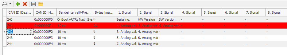
A CAN message may contain a maximum of 8 bytes of data. This is a limitation of the CAN protocol (Wikipedia).
If too many bytes have been assigned to a CAN message, optiCONTROL marks this message in red.
Module Info (read only)
Information about the module is displayed in the module info. This information is read-only.

| Field | Description |
|---|---|
| Current board temperature [°C] | The current temperature of the 8X24. |
| Module variant | The exact name of the module. |
| Internal sampling rate [Hz] | The internal sampling rate of the module's sensors. Has no influence on the transmission frequency of CAN messages. |
| Current module time [UTC] | The current time in UTC as stored in the module. Is set automatically when connected to optiCONTROL. |
By clicking the "Refresh" button in the "Current board temperature" and "Current module time" fields, the value is requested again from the module and displayed.