smartCORE Configuration
Overview
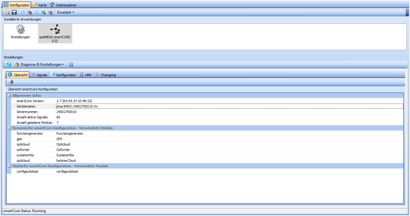
In the Overview tab you will find basic information about your smartCORE device. For example, the installed version of the smartCORE and the serial number of the device are noted here, but modules used can also be determined at a glance.
Diagnostics & settings
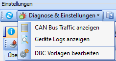
You will find three options under "Diagnostics & settings":
| Option | Description |
|---|---|
| Display CAN bus traffic | Opens a pop-up in which the current CAN bus traffic is displayed. |
| Display device logs | Opens a pop-up in which the logs of the device can be read and filtered. |
| Edit DBC templates | Opens a pop-up in which the DBC templates stored in optiCONTROL can be edited. |
Signals
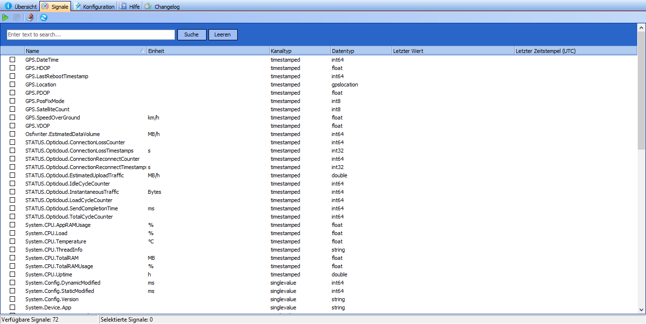
All signals produced by the smartCORE are listed in the "Signals" tab.
By selecting signals and clicking the "Play" button, the current values of the selected signals can be displayed. This value is updated with a frequency of 1Hz.
Using the input field, the list can be filtered by signal name and by clicking on the export button ![]() , the list can be exported as an Excel file.
, the list can be exported as an Excel file.
Configuration
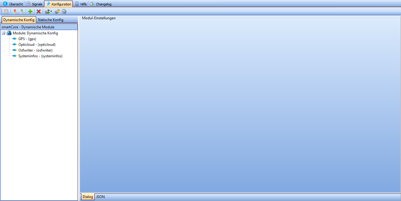
smartCORE modules can be managed and set up in the Configuration tab.
Typical systems can be set up quickly and easily using the configuration wizard, but every detail can be customized.
If you want to set up a fleet of devices, modules that have already been configured can be saved as templates and added for each subsequent device at the touch of a button.
The "Static config" area is read-only and is generally only used by optiMEAS employees.
| Icon | Description |
|---|---|
| Start configuration wizard | |
| Write current configuration to file | |
| Import configuration from file | |
| Add module | |
| Remove module | |
| Adds the module of the selected template to the config | |
| Create template | |
| Edit template |
Each module can be set up via a JSON input and for most modules optiMEAS also provides a graphical setup dialog. The graphical configuration of the most popular modules is documented in the following section.
The title of each section contains a link to the more detailed documentation of the module.
This section is still under construction. In the future you will find information on the configuration of other modules here.
You can find information on configuring modules via JSON here.
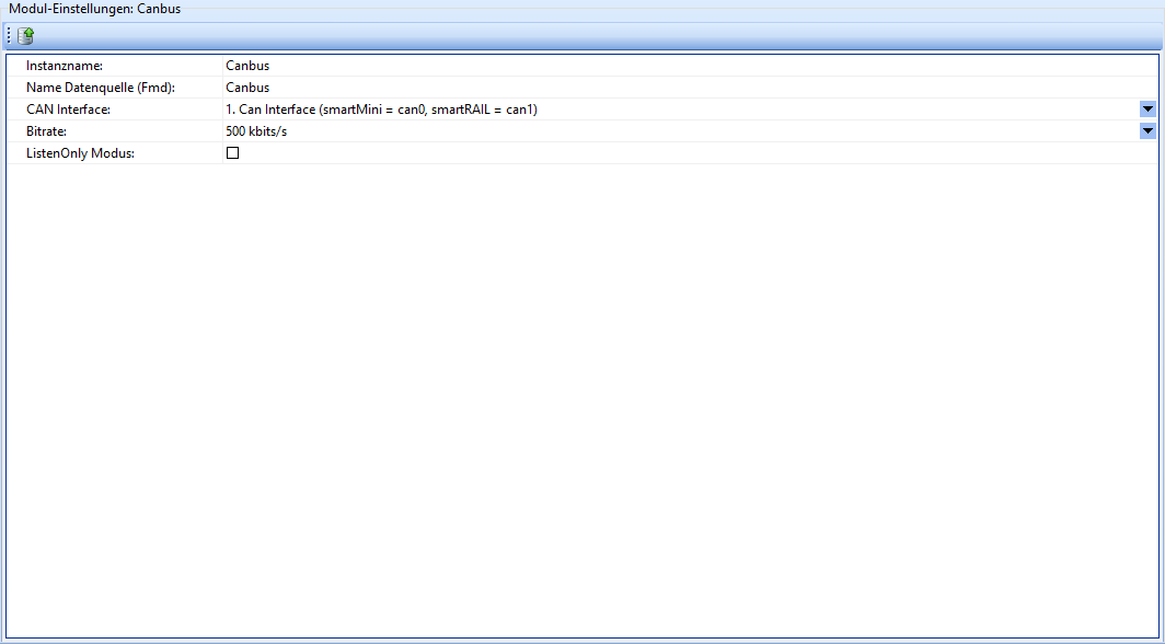
Canbus
The Canbus module provides the CAN bus hardware interface via Fast Message Dispatcher.
| Field | Description |
|---|---|
| Instance name | The name of the instance of this module. Attention: Each instance name must be unique. |
| Data source name (Fmd) | User-defined name of the data source. |
| CAN Interface | Which CAN interface is to be monitored by this module. |
| Bit rate | The bit rate of the CAN bus. |
| ListenOnly Mode | If activated, the smartCORE device behaves as a passive listener. |
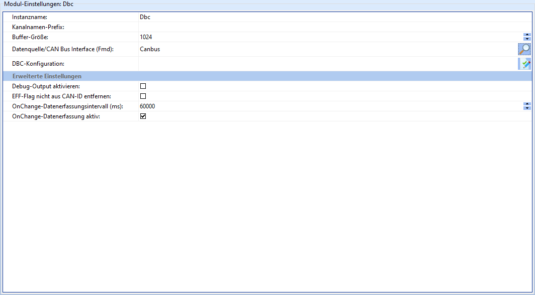
Dbc
The Dbc module provides a DBC parser via Fast Message Dispatcher.
| Field | Description |
|---|---|
| Instance name | The name of the instance of this module. Attention: Each instance name must be unique. |
| Channel name prefix | String with which all channels produced by the module should begin. |
| Data source/CAN bus interface (Fmd) | Which CAN bus interface is to be evaluated. |
| DBC configuration | Text field in which the DBC configuration to be used can be entered. |
| Activate debug output | If activated, debug information is written to the smartCORE logs. Should not be activated in normal operation. |
| Do not remove EFF flag from CAN ID | If activated, the EFF (Extended Frame Format) flag is not removed from CAN IDs. |
| OnChange data acquisition interval (ms) | Sends the current value of the signal after the specified interval, even if it has not changed. |
| OnChange data acquisition active | If activated, data is only written to the smartCORE channel if the data of the CAN message has changed. |
EventCounter
The EventCounter module provides the functionality to count events (e.g. falling below/exceeding limit values) in measurement data.
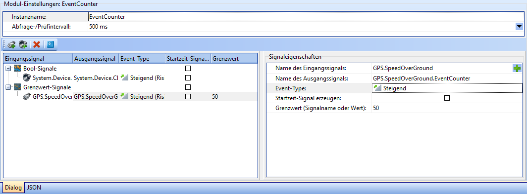
The setup interface of the EventCounter module is divided into three areas. General module settings can be configured in the upper area:
| Field | Description |
|---|---|
| Instance name | The name of the instance of this module. Attention: Each instance name must be unique. |
| Query/check interval | The interval after which the assigned input signals are to be checked. |
Signal table
The signal table is located in the bottom left-hand area. All signals to be monitored by the module are listed here. A distinction is made between bool signals and limit value signals.
There are a few buttons in the top left-hand corner of the area that are used to manage signals:
| Icon | Description |
|---|---|
| Adds a bool signal. | |
| Adds a threshold signal. | |
| Deletes the selected counter signals. | |
| Resets all counter signals defined in this module to 0. |
The table itself is read-only and provides an overview of the properties of the counter signals. These can be selected by clicking and set up in the [Signal properties area](#signal properties). The meanings of the columns are also explained there.
Signal properties
The signal properties are located in the bottom right-hand area. The properties of selected counter signals can be set here.
| Field | Description |
|---|---|
| Name of the input signal | The name of the signal to be evaluated. |
| Name of the output signal | The name of the signal that is to count the events. |
| Event type | The type of event for which the counter is to be incremented. Possible values: Rising, Falling, Rising & Falling. |
| Generate start time signal | If activated, a signal is generated that indicates when the count has started. |
| Limit value (signal name or value) | The limit value, or a signal that indicates the limit value. This field has no effect on bool signals. |
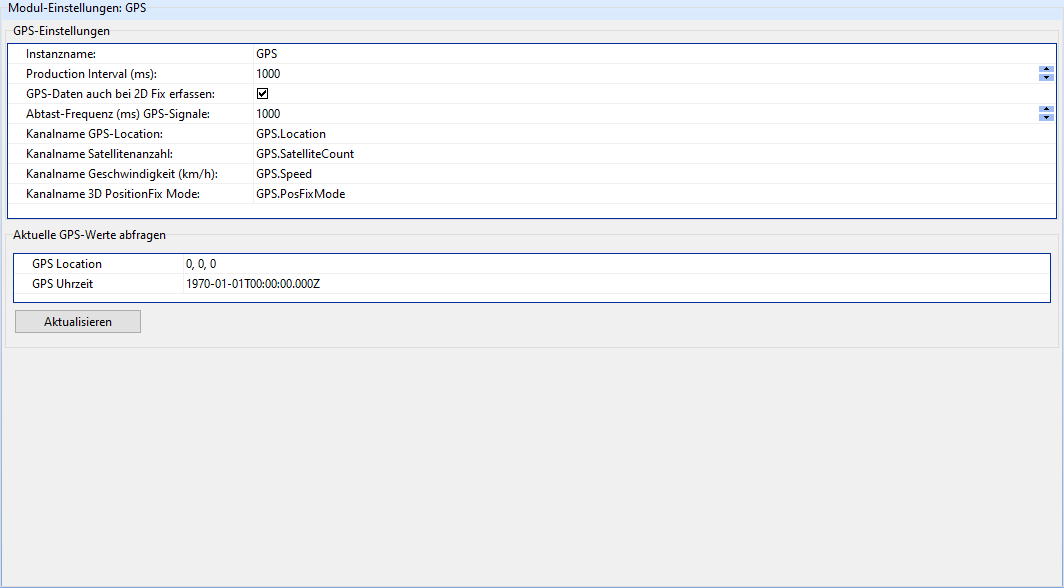
GPS
The GPS module reads and interprets GPS messages from a serial interface and produces GPS data in corresponding smartCHANNELs.
| Field | Description |
|---|---|
| Instance name | The name of the instance of this module. Attention: Each instance name must be unique. |
| Production Interval (ms) | The time in ms after which new GPS data should be written to the smartCORE channels. |
| Capture GPS data even with 2D fix | If activated, GPS data is also captured if only altitude and latitude could be determined. 3D fixes are usually more precise, but require signals from more GPS satellites. |
| Sampling frequency (ms) GPS signals | After which time in ms the GPS signals should be read out again. |
| Channel name GPS location | The name of the smartCORE channel in which the GPS position is to be output. |
| The name of the smartCORE channel in which the number of currently detected GPS satellites is to be output. | |
| Channel name Speed (km/h) | The name of the smartCORE channel in which the current speed is to be output. |
| Channel name 3D PositionFix Mode | The name of the smartCORE channel in which the current 3D PositionFix mode is to be output. This value can be interpreted as a kind of quality indicator. |
The 3D PositionFix mode can assume the following values:
| Value | Meaning |
|---|---|
| 0 | Initialization |
| 1 | No GPS |
| 2 | 2D Fix |
| 3 | 3D Fix |
Math
The Math module enables the smartCORE to perform a variety of calculations on the data set.
It is recommended that you familiarize yourself with the language before working with the Math module, as this section only describes the module's setup interface.
The complete description of the module functions can be found here.
The configuration of the Math module is divided into four tabs: Formula Code, Settings, Resources and Log Outputs.
Formula code
The formula code tab is the heart of the Math module. Formulas are programmed and checked here. The interface is divided into two areas: Code and Output of code check.
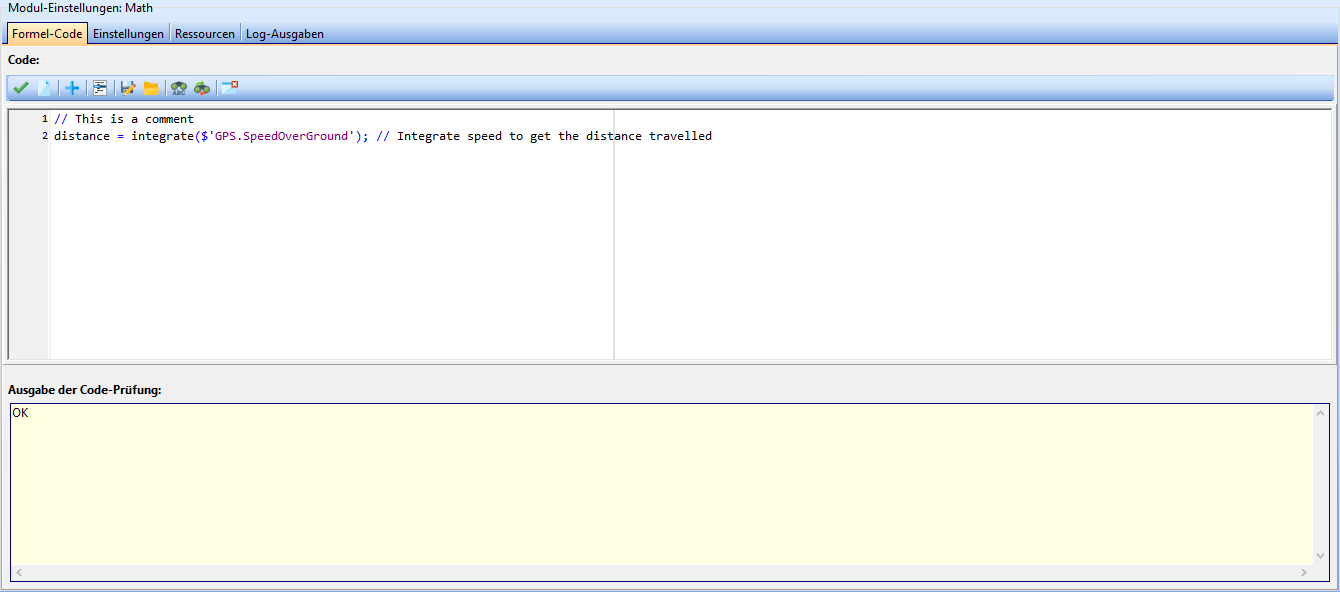
Code
In the top left corner of the code area there are a few buttons that are used to edit the formula code.
| Icon | Description |
|---|---|
| Checks the syntax of the code. The results of the check are displayed in the code check area. | |
| Deletes the output of the code check. This also includes the entries in the variables area. | |
| Opens a popup from which a signal can be selected. This is then inserted into the code. | |
| Comments or comments out the selected code. | |
| Saves the code to a file. | |
| Loads code from a file. | |
| Opens a popup where you can enter a search term to be found in the code. | |
| Opens a popup in which a search term and a replacement term can be entered. | |
| Hides the output of the code check. |
The code input field is located below these buttons. This is a free text field.
Output of the code check
The results of the syntax check of the code are displayed in this area.
By default, this area is collapsed and opens when an error is found.
If everything is OK, "OK" is displayed on a green background.
If errors are found, the type of error and the expression in which the error was found are displayed. The background turns red.
As the Math module is currently still a preview, it is possible that the version of the math library in optiCONTROL does not match the version in smartCORE.
In such a case, the code check may erroneously output an error or an OK.
Therefore, please make sure that optiCONTROL is up to date.
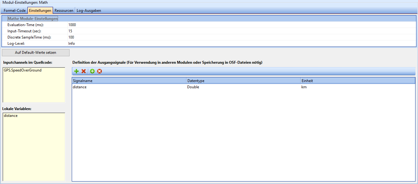
Settings
The Settings tab contains general settings for the module, as well as the variables used in the code and the definition of the output signals.
| Field | Description |
|---|---|
| Storage-Prefix | Some functions can store parameters persistently on the device. By default, these are created as invisible signals. If you need access to these signals, you can enter a new prefix here under which the parameters should be found. |
| Evaluation-Time (ms) | Time after which the formulas are to be evaluated. |
| Input-Timeout (sec) | Timeout after which the system no longer waits for channel data but continues the calculation using the last channel value. |
| Discrete SampleTime (ms) | Spacing of the underlying temporal grid over which the discrete-time calculation/evaluation of recursive formula parts takes place |
The settings can be reset to their default values using the "Set to default values" button under the settings.
Variables
This section lists local variables and input channels found in the code after a syntax check. These lists are read-only and are only used to provide a better overview of the code.
This area can also be used to ensure that no invalid variables are created, e.g. due to typing errors.
Definition of the output signals
In the top left-hand corner of the output signals area, you will find a few buttons that are used to define output signals.
| Icon | Description |
|---|---|
| Adds an output signal. | |
| Deletes the selected output signal. | |
| Adds all missing output channels from the source code. | |
| Removes all signals that are not contained in the source code. |
The main part of the output signals area is a table in which output signals are listed. The name, data type and physical unit can be set for each signal here.
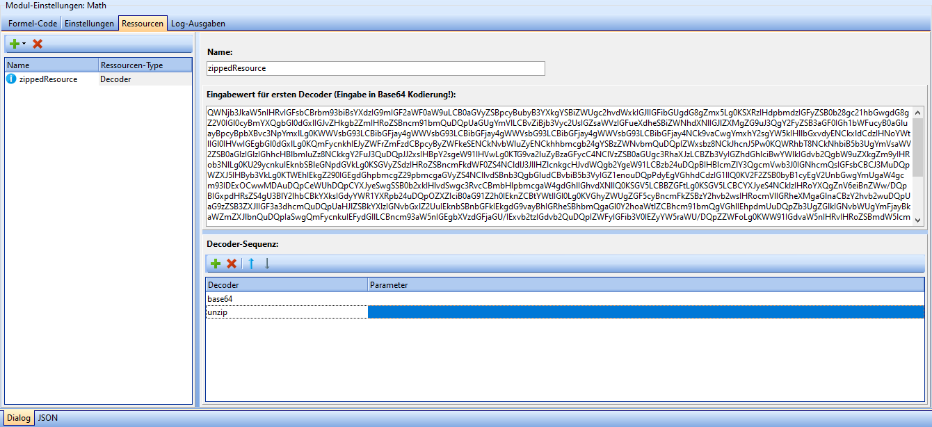
Resources
Static resources can be stored in the Resources tab, which can later be used by the Math module for calculations, e.g. a lookup table.
| Icon | Description |
|---|---|
| Add new resource (Opens dropdown). | |
| Remove selected resource. |
Three different types of resources are currently supported: JSON, text and decoder resources. Each resource must be assigned a unique name. The input dialog is designed differently depending on the resource type:
- JSON resources are entered in a JSON text field, the syntax of which is checked automatically.
- text resources are entered in a free text field.
- decoder resources are entered in a free text field, under which the decoder sequence can be created.
A new decoder can be added by clicking the '+' button and the selected decoder can be removed by clicking the 'X' button. The arrow buttons can be used to move decoders one position up or down in the sequence.
The type of decoder can be changed by clicking on an entry in the "Decoder" column. Any parameters for the decoder can be entered in the "Parameter" column.
Log output
Messages and debug information from the module are displayed in the log output tab. These are usually not necessary to put the module into operation.
The output window can be cleared by clicking the "Clear logs" button.
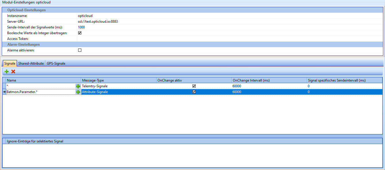
optiCLOUD
The optiCLOUD module manages the connection between smartCORE and optiCLOUD.
| Field | Description |
|---|---|
| Instance name | The name of the instance of this module. Attention: Each instance name must be unique. |
| Server URL | The URL of the optiCLOUD instance to be communicated with. |
| Transmission interval of signal values (ms) | The interval at which real-time data is to be transmitted to optiCLOUD. Does not affect the transmission frequency of high-resolution historical data (.osf files). |
| Transmit boolean values as integer | If activated, boolean values (true/false) are transmitted as an integer (1/0). |
| Broker-UserID (AccessToken) | AccessToken assigned to the device in optiCLOUD. **No connection is possible without a valid token. |
| Enable alarms | If enabled, alarms generated by other modules (e.g. diagnostics) are transmitted to optiCLOUD. |
Signals
In this section, you can specify which signals are to be sent to optiCLOUD.
By using the * placeholder, groups of signals beginning with the same name can be selected.
| Field | Description |
|---|---|
| Name | Names of the signals to be transmitted. You can use * as a placeholder here. |
| Message-Type | Telemetry-Signals/Attribute-Signals/Send as Telemetry and Attributes |
| OnChange active | If active, signals are only transmitted if their value has changed. |
| onChange Interval(ms) | Sends the current value of the signal after the specified interval, even if it has not changed. |
| Signal specific send interval (ms) | Interval after which this specific signal should be sent. If onChange is active, this should be 0. |
Signals can be added by right-clicking in the "Ignore entries for signal" window, that should not be transferred to optiCLOUD, even if they were included in the placeholders of the signal window.
Shared attributes
Shared attributes can be defined and set up in this section. Shared attributes are values that are not determined by measurement data and whose history is not recorded. Shared attributes can be changed from both smartCORE and optiCLOUD and can be used to communicate between the two. This makes it possible, for example, to change settings without having to reconfigure the device.
| Field | Description |
|---|---|
| Name | Name of the attribute. |
| Data type | Data type of the attribute. Possible values: Boolean, integer, double, string. |
| Unit | Physical unit of the attribute. |
| Save value persistently | If activated, the last value of the attribute is saved in the device. This is useful, for example, if no connection to optiCLOUD can be established after a device restart. |
| Buffer size | The size of the buffer for the history of the attribute. Usually does not need to be adjusted. |
GPS signals
GPS signals that are to be transmitted to optiCLOUD can be defined in this section. GPS signals usually originate from the GPS module, but can also be generated by the Math module or read from other devices.
The "Plus" button can be used to add a new GPS signal and the "X" button can be used to delete the selected signal.
For optiCLOUD, unique names must be assigned to the three coordinates that make up a GPS signal.
By default, these are "Longitude", "Latitude" and "Altitude".
| Field | Description |
|---|---|
| GPS location signal | smartCORE signal to be transmitted to optiCLOUD. |
| Name Longitude | What name the longitude value should have in optiCLOUD. |
| Name Latitude | What name the latitude value should have in optiCLOUD. |
| Name Altitude | What name the altitude value should have in optiCLOUD. |
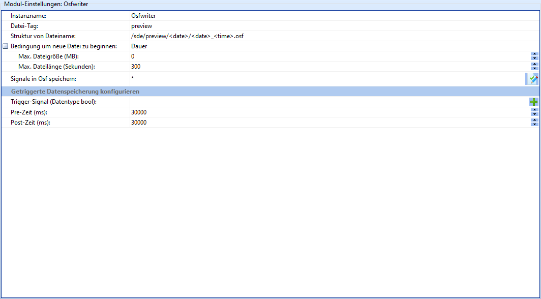
Osfwriter
The Osfwriter module is responsible for writing data recorded by sensors to OSF files.
| Field | Description |
|---|---|
| Instance name | The name of the instance of this module. Attention: Each instance name must be unique. |
| File tag | Identifier of the files created by this instance |
| File name structure | Determines the structure of the file names and the storage location on the device. Here <date> and <time> can be inserted as placeholders. |
| Condition to start new file | Determines how to determine whether a new OSF file should be created. Possible values: file size, duration. |
| Max. File size (MB) | File size in Mb of the current OSF file after which a new OSF file is to be created. |
| Max. File length (seconds) | File length in seconds of the current OSF file after which a new OSF file is to be created. |
| Save signals in OSF | Which signals from this module instance should be saved as an OSF file. Here * can be used as a placeholder. |
Triggered data storage
It is also possible to activate the storage of OSF data based on an external trigger. This is used, for example, to save higher-resolution data in the event of a fault than in normal operation.
| Field | Description |
|---|---|
| Trigger signal (data type bool) | The name of a boolean signal that is to trigger data storage. |
| Pre time (ms) | Length of the time period before the trigger signal from which data is to be written to the OSF file. |
| Post time (ms) | Length of the period after the trigger signal from which data is to be written to the OSF file. |
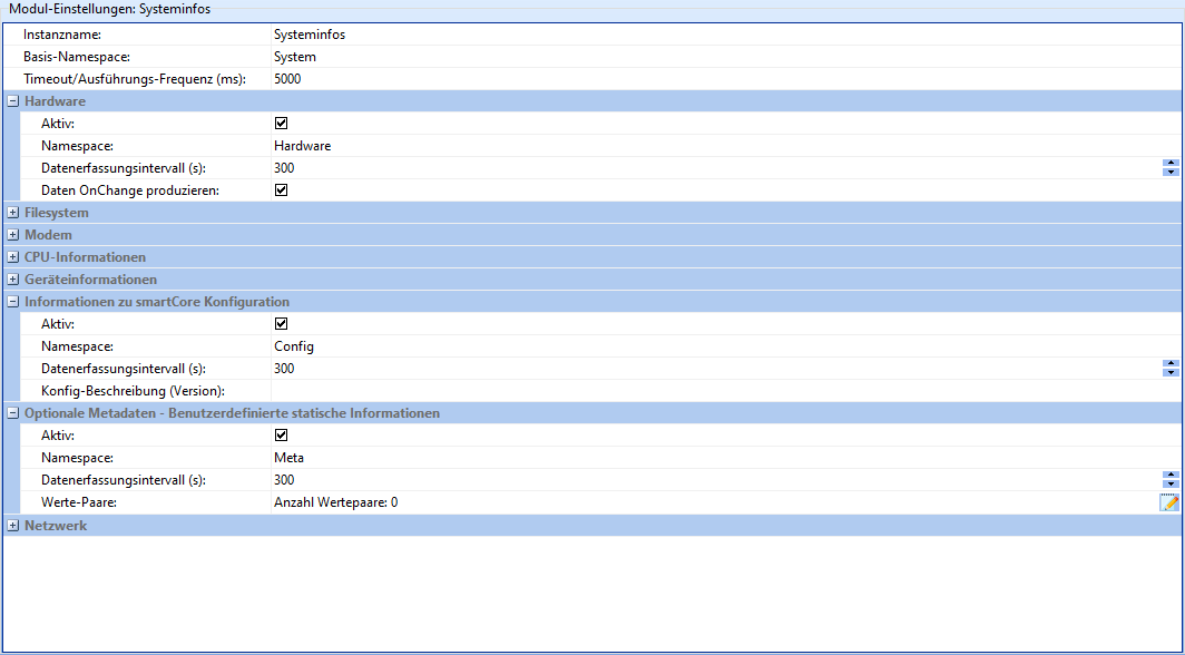
Systeminfos
The task of the Systeminfos module is to provide information about the hardware and software of the device. It is divided into 8 sections, which can be activated and configured individually.
As some fields are repeated, each field is only described once in the following table.
| Field | Description |
|---|---|
| Instance name | The name of the instance of this module. Attention: Each instance name must be unique. |
| Base namespace | String with which all channels should begin. |
| Timeout/execution frequency | Sets the maximum polling rate of the submodules and must therefore not be greater than the data acquisition interval of the submodules. If the correct frequency is unclear, it is recommended to use the default settings. |
| Active | Whether the corresponding submodule should be active. |
| Namespace | String with which the channels of the submodule should begin. |
| Data acquisition interval (s) | Time in seconds after which new data should be acquired. |
| Produce data OnChange | If active, produces data not only at interval, but also when a change is detected. |
| Monitor status of SD card (sde) | Whether data should also be collected via the external memory. |
| Config description (version) | Free text field to describe the current configuration version of the device. |
| Value pairs | Add/remove user-defined static information by clicking on the "Edit" icon. |
| Minimum file size (kByte) | File size in kByte from which files are to be counted as uploads. |
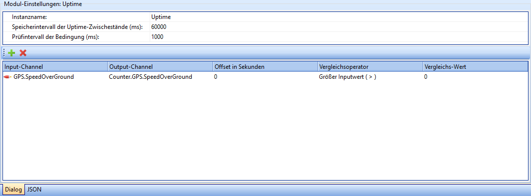
Uptime
The Uptime module makes it possible to determine how long signals assume a certain value (range).
| Field | Description |
|---|---|
| Instance name | The name of the instance of this module. Attention: Each instance name must be unique. |
| The interval in ms after which the intermediate status of the uptime counters should be saved. | |
| Check interval of the condition (ms) | The interval after which it should be checked whether the input channels still fulfill the set condition. |
The + button can be used to add further channels to be monitored.
By clicking the X button, the currently selected channel is removed from the list.
| Column | Description |
|---|---|
| Input-Channel | The name of the channel to be checked. |
| Output-Channel | The name of the channel to which the results are to be written. |
| Offset in seconds | The value entered here is added once to the counted uptime. This is used, for example, to add the previous runtime to the digitally recorded one. |
| Comparison operator | Which operator is used to compare the input channel with the comparison value. [Possible values: See below](#comparison operators) |
| Comparison value | Static value with which the input channel is to be compared. |
Comparison operators
| Operator | Symbol |
|---|---|
| greater-than or equal to input value | >= |
| less-than-equal input value | <= |
| Equal input value | == |
| Input value equal/unequal 0 | Boolean expression |
| Greater input value | > |
| Smaller input value | < |
| Not equal to input value | != |
Help
Here you will find the description stored in smartCORE for each module.
Changelog
Here you will find the changelog of the smartCORE as it is stored on the device. You can find a current version of the changelog here.