Rulechain Basics
Rulechain Basics
The Rulechains section is the heart of rule-based data processing in optiCLOUD. Even though many of the platform’s functions are configured via interfaces such as Devices, Dashboards, or Automation, the actual response and processing logic often takes place in the Rule Engine.
Therefore, changes to rulechains should always be made with caution. Faulty rules or unclear connections can have a direct impact on data processing, alerts, notifications, or integrations.
Overview
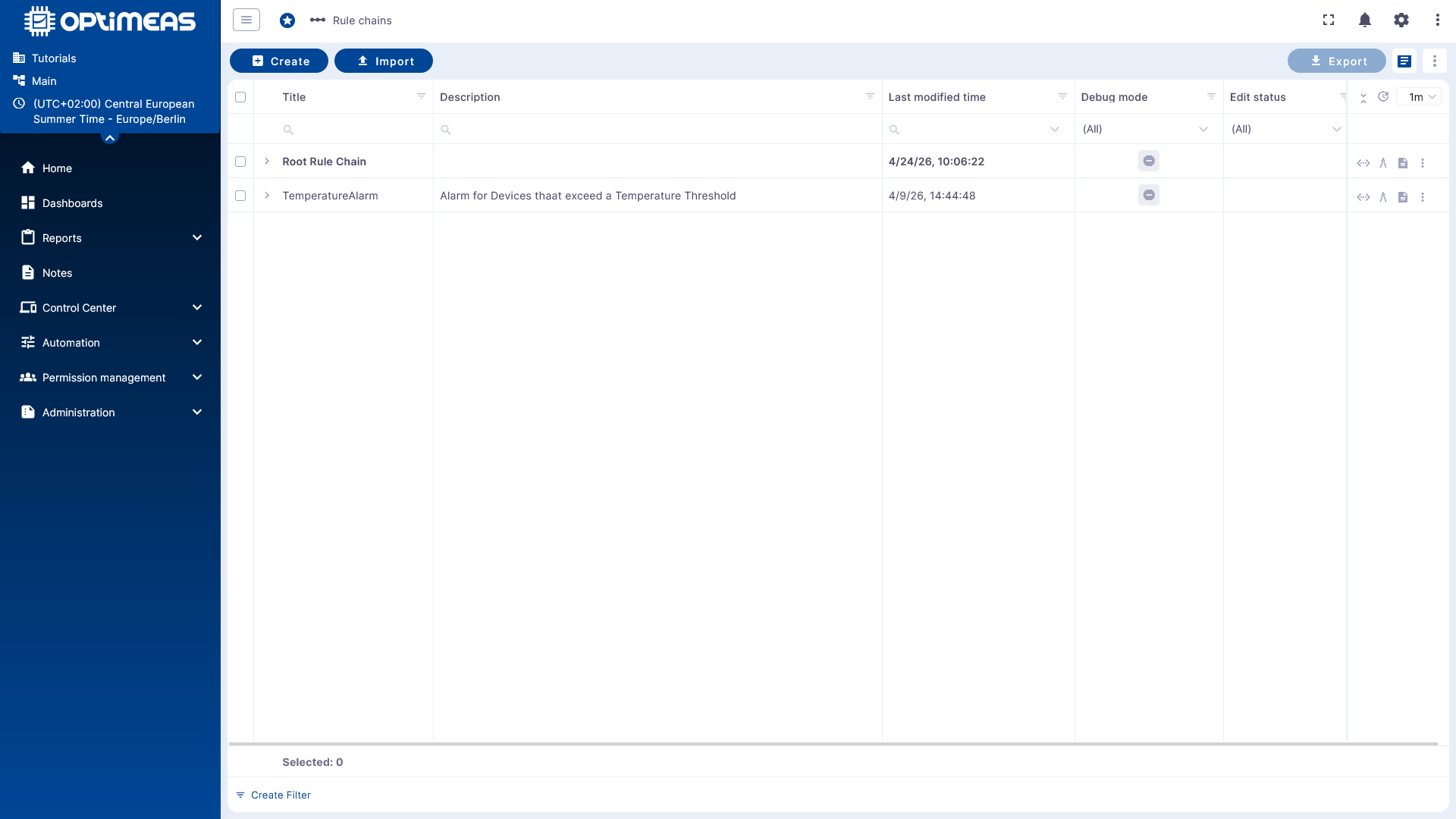
The Rulechain area overview displays the existing rulechains in a table.
The following basic principles apply:
- The Root Rule Chain is the central active entry chain.
- It is usually clearly highlighted.
- Other rule chains are initially only templates or sub-chains.
- They only become active when they are set as the Root Rule Chain or embedded in an active rule chain.
Using the action bar, rule chains can be:
- created
- imported
- exported
- deleted
.
Basic Principle of the Rule Engine
The Rule Engine is the central mechanism for processing events and data in optiCLOUD. Among other things, it processes:
- Telemetry data
- Attributes
- RPC requests
- Device lifecycle events
- REST-based events
- Files
- Logs
The Rule Engine is based on three main components:
- Message as an incoming event or data object
- Rule node as a processing step
- Rule chain as a connection of multiple nodes into a workflow
Messages
A Rule Engine message is a serializable, immutable data structure that describes an event in the system.
Examples include:
- Incoming telemetry from a device
- Attribute update
- RPC call
- Entity event such as created, updated, or deleted
- Status events such as connected, disconnected, active, or inactive
A message contains:
- Message ID
- Sender or origin of the message
- Message type
- Payload as a JSON body
- Metadata as additional key-value pairs
Rule Node
A rule node processes an incoming message and generates one or more outgoing messages or actions from it.
Depending on the node type, a node can:
- Filter messages
- Transform data
- Enrich data
- Generate or delete alerts
- Call external systems
- Forward messages to other nodes
This makes each node a clearly defined logical unit within the rule chain.
Connections and Relationships
Rule nodes are linked to one another via connections. Each connection has a relationship type that determines under which conditions a message is passed on to the next node.
Typical relationship types are:
- Success
- Failure
- True
- False
Depending on the node type, other designations may also be used, for example:
- Post Telemetry
- Attributes Updated
- Entity Created
This allows the business meaning of a data flow to be represented directly in the rulechain.
Key Features of Rulechains
Rulechains offer several key features in optiCLOUD:
- Stream processing for data and events arriving in real time
- Workflow structure through connected rule nodes
- Flexibility through integrated nodes and user-defined scripts
- Integration capability via HTTP, MQTT, Kafka, or other interfaces
- Reactivity for alerts, notifications, and follow-up actions
This allows for the modeling of both simple filter rules and complex automation workflows.
Typical use cases
Rulechains are used for tasks such as:
- Validation and transformation of incoming data
- Alarm management and notifications, e.g., for exceeding or falling below thresholds
- Monitoring the device lifecycle
- Integration of external systems or transfer to external data pipelines or platforms
- Remote control via RPC
How it works in the editor
When a rulechain is opened, a low-code editor based on nodes and connections appears. The structure is reminiscent of tools like Node-RED or n8n.
Within this editor, you define:
- Which messages enter the chain
- Which conditions are checked
- Which actions are triggered
- How success or error paths proceed
Base RuleChain
The Basic RuleChain, also known as the Root RuleChain, forms the foundation of data processing and is already set up by default. It looks like this:
Every incoming message from a device enters the system via the input node and is immediately forwarded to a message type switch, which determines how the message should be processed based on the message type.
From there, processing branches into several specialized paths:
Core message processing
| Message Type | Forwarding | Receiving Node | Explanation |
|---|---|---|---|
| Post Attributes | Save to Client Attributes | Save Client Attributes | Messages of this type are processed to permanently store device attributes in the database. |
| Post Telemetry | Save to Time Series | Save to Time Series | Telemetry data such as sensor values are stored as time series in the database. |
| RPC Request from Device | Forwarded to Log RPC | Log RPC from Device | Used for monitoring or troubleshooting incoming RPC calls from the device. |
| RPC request to the device | to RPC Call Request | RPC Call Request | Triggers a remote procedure call to the device. |
| Send alarms | to Save Alarms | Save Alarms | Alarm states are stored in the database. |
| Miscellaneous | Log Miscellaneous | Log Miscellaneous | Unsupported or unknown message types are logged for tracking. |
| Blob storage request | Process Blob Storage | Blob Storage Processing | Starts processing file-related uploads in file storage. |
Example
A simple, straightforward example is a good starting point for practical implementation. One such example is an alert triggered when a temperature threshold is exceeded.
Continue to the example rule: