Topic: Inrush current
Fusing the current input
The fuse (500mA, fast-acting) in the measurement path of the current input is intended to protect the measurement input from damage caused by incorrect wiring. It may only be replaced by optiMEAS Service (subject to a fee)! To avoid unnecessary downtime and costs, the wiring must be carefully checked before commissioning!
Why does the smartIO 8x24 have a 500mA fuse?
Measuring terminals in industrial applications for 4-20mA sensors typically have an integrated shunt of , at which the voltage drop is recorded as a measurement signal.
If is incorrectly connected to the measurement input without a sensor, a power loss of approx. would occur at the shunt. This may be tolerable for a certain period of time.
Incidentally, this resistance limits the inrush current of the connected sensor or measuring transducer to approx. 240 mA when internal buffer capacities need to be charged.
However, the smartIO 8x24 continuously measures currents up to 200 mA (plus a tolerance range of 50%). This means that the shunt resistance must be significantly smaller in order to minimize both power loss and voltage drop. This optimization has an impact on fault protection.
If supply voltage is accidentally applied directly to the input (I_IN, COM), a current flows through the measuring shunt without appropriate fusing
This means a power loss of
This would lead to considerable, irreparable damage to SMD components and the circuit board after a very short time. In order to at least maintain reparability, a chip fuse is therefore provided in the confined installation space, which interrupts excessive current flow within a millisecond.
In addition, this fuse must function reliably in the extended temperature range of the smartIO 8x24 and be housed in a very confined space, virtually potential-free, at the high-impedance measurement input. This rules out many alternative solutions, also in view of the price of the module.
How can damage be detected?
It quickly becomes apparent in the measurement data if a measurement channel configured for current measurement only delivers zero values, regardless of the measurement range. Minimal noise may still be observed. If a 4–20 mA sensor or measuring transducer is connected, this value is certainly beyond the valid measurement range and can be detected as an error.
To detect a fault, the resistance between the I_IN and COM connections of a channel can be measured with a multimeter. If this is in the range , the input is functional and the fault is more likely to be found in the wiring or sensor supply. If it is significantly higher or infinite, the smartIO 8x24 must be repaired by the optiMEAS service (subject to a fee).
Inrush current of a sensor or measuring transducer
Some sensors or transducers that are connected using two-wire technology and carry the measurement signal and the supply voltage via the same pair of wires have such large internal buffer capacities that a current peak significantly above 500mA can occur during the switch-on process! This is only very short and cannot be detected with a normal multimeter, but it is sufficient to trip the fuse at the input.
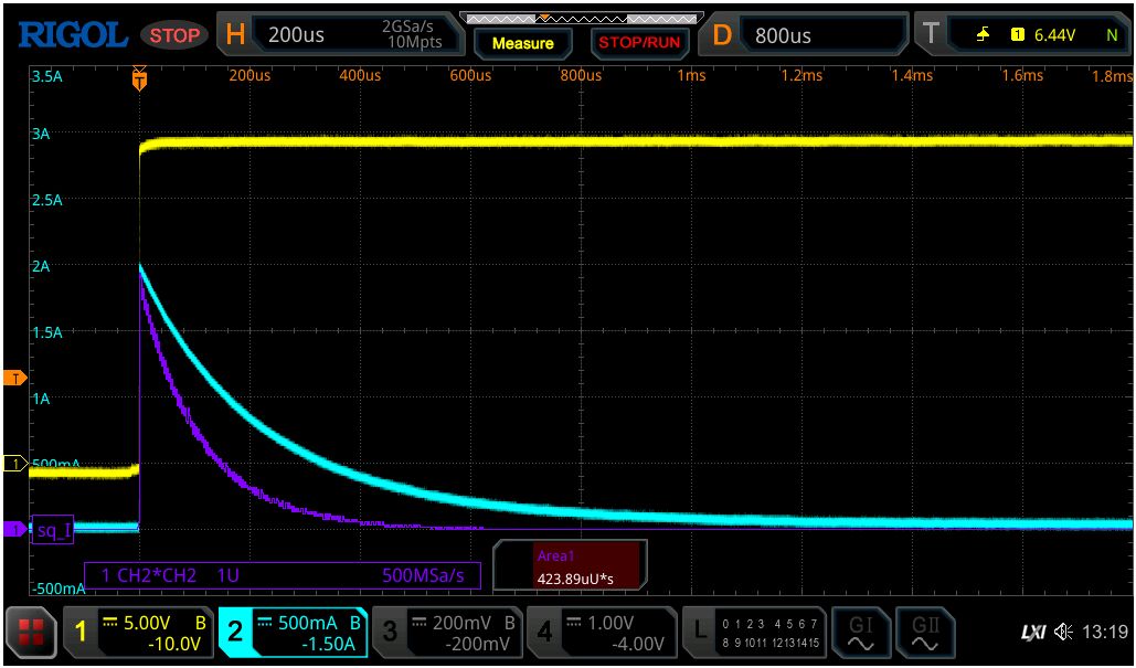
This oscillogram shows the switch-on process of a measuring transducer with a supply (yellow) and a current peak of up to (cyan) on a shunt. The energy input (purple + area calculation) into the fuse is already close to the trip limit at .
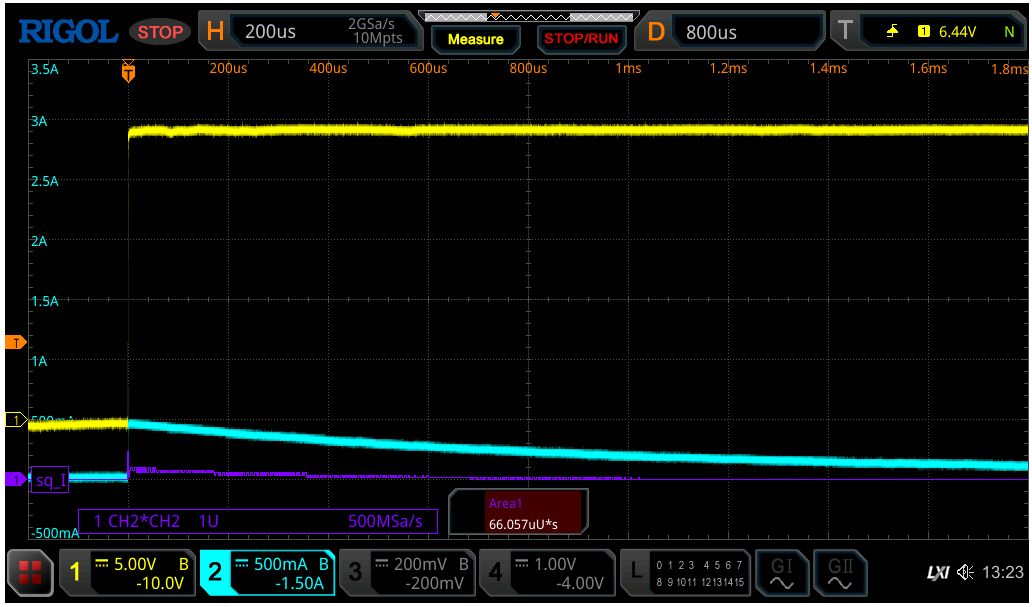
As a rule, the current peak can be significantly reduced by adding another current-limiting series resistor of approx. 50 to 100 ohms in the measuring line without restricting functionality.
A series resistor of already reduces the peak to 500mA and the energy input to a tolerable .