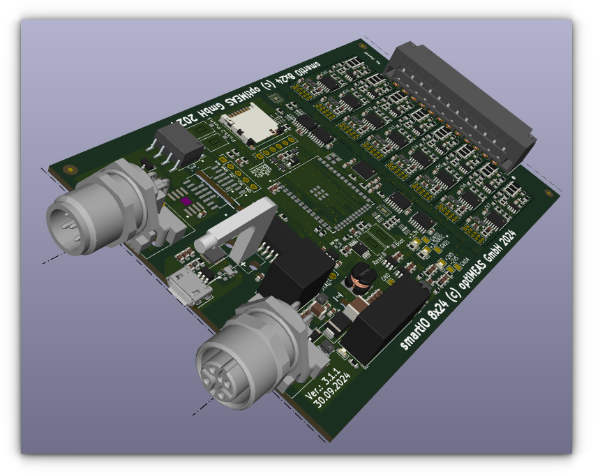
smartIO 8x24
Description
The smartIO 8x24 offers connection options for 8 analog signal sources for voltage or current measurement with the following selectable measuring ranges:
- ±160V, ±80V, ±40V, ±20V, ±10V, ±5V
- ±200mA, ±100mA, ±50mA, ±25mA, (Fused with 500mA)
Other key parameters are
- Sampling rate up to 1 kHz
- 24-bit analog-to-digital converter
- Common-mode voltage up to 100V
- Current input with overload protection
- Sensor linearization via polynomial
- Various filter options
- Isolation between process, supply, and digital interfaces up to 1700 V DC
The module is configured via a serial interface (USB) and the extensive SCPI command set using any terminal program or, preferably, optiCONTROL. This configuration also includes the addresses, transmission rates, and assignment of CAN messages. Configuration in the field can be carried out via the CAN bus using the smiocan console application. This is included in the current versions of Yocto Linux for the smart family (smartMINI, smartRAIL, etc.).
Each module is individually tested as a RAIL version with regard to voltage resistance and insulation between the process and USB sides. With its sturdy aluminum housing and protective coating on the circuit board in accordance with EN50155, it also meets the requirements for use on rail vehicles.
Even though the module is integrated into the smartRAIL housing, the connection for CAN and power supply is made via the two M12 connectors. These can be connected in series with the smartRAIL connector using a short M12 connection cable.
optiMEAS reserves the right to make changes and errors in this and all other data, descriptions, or examples relating to this product.
Function

The smartIO 8x24 has 8 inputs, each of which has an identical structure:
-
The voltage input connections (U_IN, COM) are each connected with a high impedance of , an operating mode selector switch, and the subsequent input amplifier with Sallen-Key filter (SKF).
-
The connections of the current input (I_IN, COM) are connected to each other via a fuse (F)1 for overload protection and a small shunt resistor . The voltage tap on the shunt has a high impedance of and leads via the operating mode selector switch to the subsequent input amplifier with Sallen-Key filter (SKF).
warningThe connection instructions in the Current Measurement section must be observed! The fuse (500mA, fast-acting) in the measurement path is intended as a protective measure against destruction of the measurement input due to faulty wiring. It may only be replaced by optiMEAS Service (subject to a charge)! To avoid unnecessary downtime and costs, the wiring must be carefully checked before commissioning! To avoid damage, please also refer to this chapter!
-
The COM connections of the 8 channels are only connected to each other via the input impedances and a virtual ground point. This means that the inputs are designed for differential measurement in every operating mode. It is therefore essential to set the COM connection to a reference potential on each channel used.
-
The common-mode voltage2 between the inputs may be up to 100V DC.
-
The Sallen-Key filter limits the input bandwidth to 480 Hz and thus acts as an anti-aliasing filter for the subsequent AD converter.
-
The AD converter based on the delta-sigma method is configurable up to sampling rates of 1 kHz, synchronous for all input channels. The programmable input gain allows for different measuring ranges, the conversion width is 24 bits.
-
A calibration data set is stored for each gain and operating mode (U/I), which is used to calculate the measurement voltage or measurement current at the input.
-
This calibrated measured variable can be calculated using a user polynomial3 to map a sensor characteristic curve. This allows the module to output the physical measured variable of the sensor directly via CAN.
-
This physical measured variable is fed in parallel to various filter stages:
- a 1st order low-pass filter
- a moving average filter
- a moving RMS filter
The window width of the moving filters and the time constant for the low-pass filters can be set jointly for all channels. With a window width of 300 samples, true RMS values can also be measured directly for AC signals with typical frequencies of 50 Hz (15 periods), 60 Hz (18 periods), and 16 2/3 Hz (5 periods).
Communication
The measured values are transmitted on the CAN bus in individual messages. Up to 20 CAN messages can be configured with:
- CAN ID (11-bit, 29-bit)
- Transmission rate in ms, after device start or RTR
- Content
A wide range of data elements is available for the content, including not only the filtered measured values, but also status information about the channel, the internal temperature of the module, firmware and hardware status, or the physical unit. The measured values are preferably transmitted as 4-byte <float>, which eliminates the need for further scaling on the receiver side if the module is planned and set up accordingly. Transmission as <int16> is also possible. In this case, however, the scaling of the output variable depends on the selected measuring range or the user polynomial in order to make the best possible use of the limited value range.
Configuration is carried out using an extended SCPI protocol via the serial interface4, which is available on the USB configuration port (COM, /dev/tty). The serial interface can be addressed with any terminal program5. The module supplements an editable command input with history and offers optional color output. For certain commands that affect multiple channels simultaneously, the output is structured in a readable manner. In addition, the line ending used (CR, LF, CRLF) is determined automatically, enabling operation on a (classic) terminal. Using the __? command, a detailed, documented list of all commands can be retrieved directly from the device. Critical commands are protected by a passcode. The configuration software optiCONTROL provides easy-to-use input masks for the essential settings for configuring the module.
A service connection to the new smartIO family can also be established in the field via two reserved CAN messages (0x011, 0x012). An extended ISO-TP protocol is run via the messages. In addition to the actual data connection (ASCII/binary), asynchronous status information for connection management and command processing on the device side is also implemented. This makes it possible to select a device for communication on the same CAN messages and to transfer even large amounts of data securely and bidirectionally. Furthermore, access protection is implemented using a seed key procedure.
This service connection
- the device's SCPI command set is operated for configuration and
- a firmware update of the device software can be performed.
In the current versions of the YOCTO environment, the console application smiocan can be used on devices of the smart family for communication via this service connection. The app offers the following options:
- Perform device search
- Set device time/date
- Various logbook outputs
- Execute commands from
- the Linux command line
- a batch file or
- interactively
- Perform firmware updates for a specific device or all devices
Isolation of connection groups
The input group for supply voltage and CAN bus, the USB configuration interface, and the connections to the process are isolated from each other, suitable for use in systems with a nominal operating voltage of 110V up to an isolation voltage of 1.7kV DC.
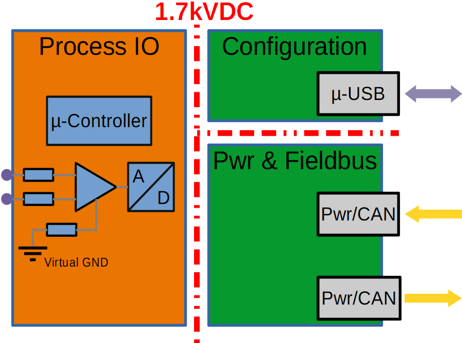
Depending on the module design, process inputs are connected with high impedance to the internal analog reference point (virtual GND) and thus – usually to a negligible extent – to each other.
Module interfaces
Measurement inputs (X10)
Double-row Phoenix terminals with a 3.5 mm pitch are used for the measurement inputs [X10]. The position of pin 1 and the counting direction are marked on the housing.
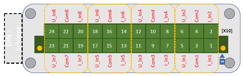
| Channel | I_IN | COM | U_IN |
|---|---|---|---|
| 1 | Pin 1 | Pin 3 | Pin 5 |
| 2 | Pin 2 | Pin 4 | Pin 6 |
| 3 | Pin 7 | Pin 9 | Pin 11 |
| 4 | Pin 8 | Pin 10 | Pin 12 |
| 5 | Pin 13 | Pin 15 | Pin 17 |
| 6 | Pin 14 | Pin 16 | Pin 18 |
| 7 | Pin 19 | Pin 21 | Pin 23 |
| 8 | Pin 20 | Pin 22 | Pin 24 |
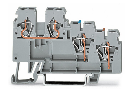
Suitable connectors from Phoenix are
The base housing of the plug connection on the smartIO and the plugs can be uniquely marked using the coding profile if several smartIO modules are used. This enables pre-assembly of the plugs and connection without confusion.
- Item no. 1790647, CP-DMC 1.5 NAT - Coding profile
Voltage measurement
The U_IN and COM inputs must be used for voltage measurement. The measurement is differential, so both connections must always be used. The potential difference between different input channels must be within the permissible common-mode voltage range.
In the smartIO configuration, deactivate current measurement for the corresponding channel (adc:current N, 0) and select a suitable measuring range (adc:gain N, G). The optiCONTROL software is recommended for configuration; configuration via the SCPI interfaces is also possible.
The following example shows the voltage measurement on any component in the process:

An active sensor with an integrated amplifier and (bipolar) voltage output can be connected as follows, for example:

The following measurement ranges can be set:
| Gain G | Measuring range |
|---|---|
| 1 | |
| 2 | |
| 4 | |
| 8 | |
| 16 | |
| 32 |
Current measurement
The fuse (500mA, fast-acting) in the measuring path is intended to protect the measuring input from damage caused by incorrect wiring. It may only be replaced by optiMEAS Service (subject to a charge)! To avoid unnecessary downtime and costs, the wiring must be carefully checked before commissioning! To avoid damage, please also refer to this chapter!
The I_IN and COM inputs must be used for current measurement. The measurement is performed differentially via the internal shunt resistor; both connections must always be used. The measurement can be performed at any position in the measuring circuit of the signal source (high/low side). The potential difference between different input channels must be within the permissible common-mode voltage range.
In the smartIO configuration, activate current measurement for the corresponding channel (adc:current N, 1) and select a suitable measuring range (adc:gain N, G). The optiCONTROL software is recommended for configuration; configuration via the SCPI interfaces is also possible.
A 2-wire sensor that modulates the measured variable as a 4-20mA current signal to the supply voltage is connected according to the following diagram:

If a sensor with an integrated amplifier and (bipolar) current output (e.g., LEM current transformer) is used, the connection is made as follows:

The following measuring ranges can be set:
| Gain G | Measuring range |
|---|---|
| 1 | |
| 2 | |
| 4 | |
| 8 |
The scaling factors 16 and 32 are not calibrated and must not be used for measurements.
For clean wiring of 2-wire sensors, the Initiator Terminal 270-560 from Wago with the appropriate accessories (power supply terminal -564, jumper -409, termination plates -319). This ensures the distribution of the supply voltage and ground return for all sensors and provides sufficient connections for the sensor cables and measurement inputs of the smartIO 8x24.
The fuse (500mA, fast-acting) in the measurement path is intended as protection against destruction of the measurement input due to faulty wiring. It may only be replaced by optiMEAS Service (subject to a charge)! To avoid unnecessary downtime and costs, the wiring must be carefully checked before commissioning! To avoid damage, please also refer to this chapter!
Sensor scaling
The measured input variables voltage or current are transmitted via the CAN bus in float format using the factory settings. Scaling to the measuring range used in the DBC file is not necessary. Scaling to the physical measured variable recorded at the sensor can be done in the DBC file or, better still, via the polynomial definition in the smartIO. The latter also enables the correct display of the true RMS values calculated in the smartIO.

The following is an example of determining the coefficients for connecting a 4-20mA pressure sensor:
The polynomial to be determined specifies the relationship between the measurement signal (voltage or current at the measurement input) and the physical measurement variable of the sensor:
The following information can be found in the sensor data sheet:
Substituting these points into the above equation, we obtain:
In this case, the following polynomial would be set in smartIO for channel N=2:
adc:polynom 2, 12.5, -100.0
adc:unit 2, "hPa"
The dialog-guided configuration using optiCONTROL is much easier:
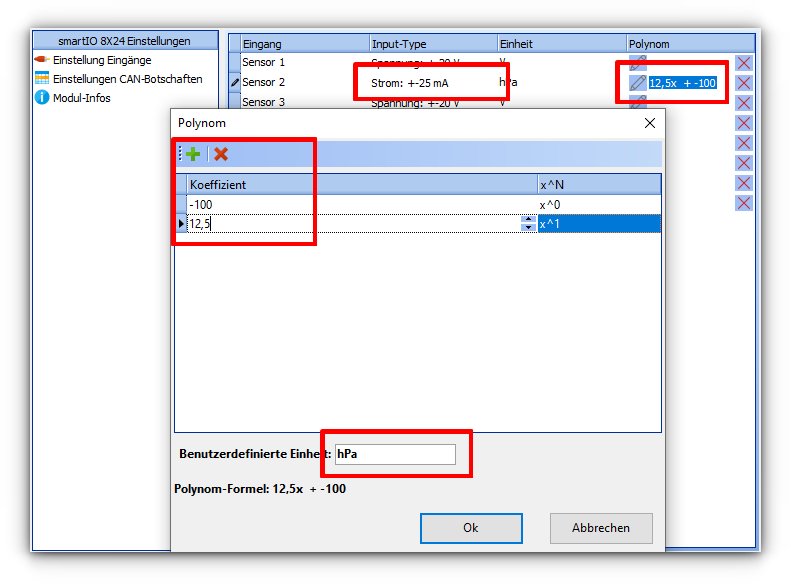
All result values on the CAN bus are then correctly scaled in hPa for this channel.
Power supply, CAN bus, configuration (X20 - X22)
The supply voltage and CAN bus are available on two M12 connectors (A coded)
[X20] and [X22] according to the Device-Net assignment. The
24V power supply is looped through from the connector
to the socket, as is the CAN bus connection. This allows several different smartIO modules to be
connected in series. If no further smartIO module follows, the
CAN bus must be terminated with a connector with integrated terminating resistor (120 Ω) or
directly at the Phoenix terminal. CAN-GND is identical to the supply ground
.
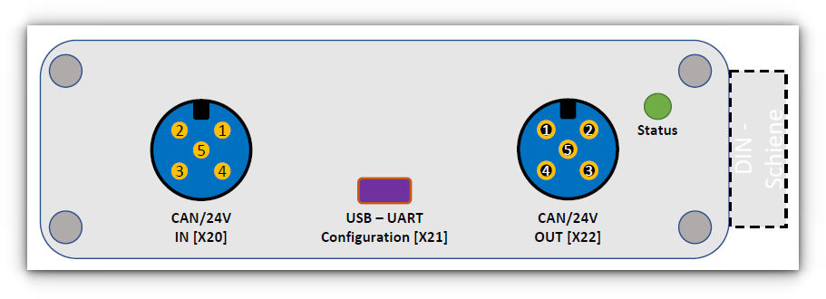
CAN In/Out (X20, X22)
The two connections [X20] and [X22] are internally connected 1:1 and have identical functions. The male/female pair design allows the CAN bus to be continued directly, bypassing the smartIO.
| Pin | Signal | Description |
|---|---|---|
| 1 | CAN shield | Cable shielding, is passed through |
| 2 | +24 V | Power supply +24V (nom., see technical data) |
| 3 | GND | Reference ground for power supply and CAN bus |
| 4 | CAN H | CAN bus: CAN high |
| 5 | CAN L | CAN bus: CAN low |
Standard Device-Net cables with female to male connectors can be used. For pre-assembled cables, twisted pair cable bundles must be selected for connection pairs 2 and 3 as well as 4 and 5.
The smartIO itself does not have an internal terminating resistor for the CAN bus. This is available as an accessory in M12 format.
For information on setting up CAN bus networks and their termination, please refer to this article.
USB (X21)
The USB-UART configuration interface [X21] conceals a USB-serial converter (CP2102N), which is mapped as a virtual COM port under Windows and as /dev/tty* and /dev/serial/by*... under Linux. This connection is also electrically isolated from the process level. The ASCII-based SCPI protocol is used to configure the module. However, we recommend using the optiCONTROL software from optiMEAS to configure the smartIO modules, as it provides a graphical user interface with appropriately prepared dialogs.
Certifications
EC Declaration of Conformity

The CE mark indicates compliance with the
- EMC Directive,
- RoHS 2011/65/EU (June 8, 2011), and the
- Low Voltage Directive.
Railway applications—Electronic equipment on railway vehicles, EN 50155:2017
| Topic | Description | Standard |
|---|---|---|
 | For the smartRAIL version, in addition to the CE declaration of conformity, the following classifications and certifications to EN50155 are also carried out: | |
 | Environmental conditions: - AX (2000m) - TX (...) - Cold - Dry heat - Cyclical humid heat | EN 50125-1 §4.2.1 EN 50155 §4.1.2 EN 50155 §13.4.4 EN 50155 §13.4.5 EN 50155 §13.4.7 |
 | Oscillations and shocks - Oscillations - Shocks | IEC61373 §8 + 9 IEC61373 §10 |
 | EMC + insulation Individual tests are performed and recorded in accordance with EN50155 §12.2 - Visual inspection - Insulation 500V DC - Withstand voltage 1.7kV | EN50121-3-2 EN 61000-3-2/3 EN 55016-2-1/2 EN50155 §12.2.1 EN50155 §12.2.9.1 EN50155 §12.2.9.2 |
 | Fire protection | EN45545-2 |
Technical data
Supply voltage / Ambient conditions
| Parameter | Comment | Min | Type | Max | Unit |
|---|---|---|---|---|---|
| Supply voltage | with reverse polarity protection | 8 | 36 | V | |
| Overvoltage protection | no | ||||
| ESD protection | TVS diode | 40 | V | ||
| Current consumption | @ 24V | 50 | 60 | mA | |
| Connector | A-coded (M + F) | M12 | |||
| Operating temperature | EN 50155 / Range TX6 | -40 | 85 | °C | |
| Relative humidity | (condensing) | 5 | 95 | % | |
| PCB coating | EN50155 | PC2 | |||
| Housing | Aluminum | ||||
| Length | (without connector) | 124 | mm | ||
| Width | 85 | mm | |||
| Height | 35 | mm | |||
| Weight | 330 | g | |||
| Cooling | Passive | ||||
| Protection class | ISO 20653 | IP54 | |||
| Mounting | Mounting rail (EN 50022) | TS 35 | |||
| RAIL version | |||||
| Insulation resistance | @ 500V | 10 | |||
| Withstand voltage test | 60s | 1.7 | kV |
CPU
| Parameter | Comment | Value | Unit |
|---|---|---|---|
| Processor | ESP32-S3 | ||
| Family | Xtensa® 32-bit LX7 | ||
| Clock | 240 | MHz | |
| ROM | FLASH | 384 | kB |
| RAM | SRAM | 512 | kB |
| Data bus | 32 | bit |
Analog inputs, digitization
| Parameter | Comment | Min | Type | Max | Unit |
|---|---|---|---|---|---|
| Number | Voltage, differential7 | 8 | |||
| Measuring range | Gain = 1 | -160 | 160 | V | |
| Gain = 2 | -80 | 80 | V | ||
| Gain = 4 | -40 | 40 | V | ||
| Gain = 8 | -20 | 20 | V | ||
| Gain = 16 | -10 | 10 | V | ||
| Gain = 32 | -5 | 5 | V | ||
| Accuracy | 0.02 | % FS | |||
| Input resistance | to virt. MP | 1 | |||
| Number | Current, differential7 | 8 | |||
| Gain = 1 | -200 | 200 | mA | ||
| Gain = 2 | -100 | 100 | mA | ||
| Gain = 4 | -50 | 50 | mA | ||
| Gain = 8 | -25 | 25 | mA | ||
| Accuracy | 0.50 | % FS | |||
| CM suppression | 0.05 | % FS | |||
| Shunt | , 1.5W6 | 10 | |||
| Fuse | 32V, fast Replacement only by optiMEAS Service | 500 | mA | ||
| Input resistance | to virt. MP | 1 | |||
| Anti-aliasing filter | Sallen-Key filter, 2nd order, switchable | 480 | Hz | ||
| Converter | Delta-sigma | 24 | bit | ||
| Sampling rate | 1000 | Hz | |||
| Output rate | via CAN | 0 | 1000 | Hz | |
| Software filter | Lowpass, 1st order | 0 | 1000 | ms | |
| MiWe, RMS | 300 | 500 | Samples | ||
| Linearization | Polynomial |
Interfaces
| Parameter | Comment | Min | Type | Max | Unit |
|---|---|---|---|---|---|
| Number | CAN 2.0 B | 1 | |||
| Baud rate | configurable | 500 | 1000 | kbit/s | |
| Connector | A-coded (M + F) | M12 | |||
| Terminating resistor | no | ||||
| Number | Serial/USB | 1 | |||
| Baud rate | fixed | 38400 | kbit/s | ||
| Connector | Micro-USB | ||||
| Chipset | Power supply via USB | CP2102N | |||
| Protocol | SCPI |
Both interfaces are isolated from each other and from the measurement input.
The module responds to the SCPI query *idn? with an identification according to the following pattern, whereby the serial number, version status, and date/time stamp will vary:
optiMEAS, smartIO, 8X24, 1, 24006200011, 1.35, 0, Nov 22 2024 15:50:07, 20240610
Process image
The following messages are reserved for the smartIO family with ESP controller:
| CAN ID (dec) | CAN ID (hex) | Data type | Direction | Description | Unit |
|---|---|---|---|---|---|
| 16 | 0x010 | uint48 | to all smartIO | Timestamp (Unix, 1970-01-01) | ms |
| uint8 | 0 | ||||
| uint8 | Checksum | ||||
| 17 | 0x011 | ISO-TP+8 | to all smartIO | Diagnostic interface | |
| 18 | 0x012 | ISO-TP+8 | from activated smartIO | Diagnostic interface |
The process image for measurement data and status information is freely configurable via the SCPI interface. With the factory settings, the following messages and contents are sent in Motorola format (MSB) at a baud rate of 500 kbit:
can:msg      0x0F0,    -2, 9000, 9001, 9002
can:msg      0x0F1,    10,    0,    1
can:msg      0x0F2,    10,    2,    3
can:msg      0x0F3,    10,    4,    5
can:msg      0x0F4,    10,    6,    7
can:msg      0x0F5,   100,  200,  201
can:msg      0x0F6,   100,  202,  203
can:msg      0x0F7,   100,  204,  205
can:msg      0x0F8,   100,  206,  207
can:msg      0x0FD,  1000, 8000, 8001, 8002, 8300, 8301, 8110
| CAN ID (dec) | CAN ID (hex) | Param. ID | Data type | Output clock | Description | Unit |
|---|---|---|---|---|---|---|
| 240 | 0x0F0 | 9000 | uint40 | Startup + RTR | Serial Number240062##### | |
| 9001 | uint8 | HW Version | ||||
| 9002 | uint16 | SW Version | ||||
| 241 | 0x0F1 | 0 | float | 10 ms | Input 1, PT1 filter | V, mA, X |
| 1 | float | Input 2, PT1 filter | V, mA, X | |||
| 242 | 0x0F2 | 2 | float | 10 ms | Input 3, PT1 filter | V, mA, X |
| 3 | float | Input 4, PT1 filter | V, mA, X | |||
| 243 | 0x0F3 | 4 | float | 10 ms | Input 5, PT1 filter | V, mA, X |
| 5 | float | Input 6, PT1 filter | V, mA, X | |||
| 244 | 0x0F4 | 6 | float | 10 ms | Input 7, PT1 filter | V, mA, X |
| 7 | float | Input 8, PT1 filter | V, mA, X | |||
| 245 | 0x0F5 | 200 | float | 100 ms | Input 1, RMS[300] | V, mA, X |
| 201 | float | Input 2, RMS[300] | V, mA, X | |||
| 246 | 0x0F6 | 202 | float | 100 ms | Input 3, RMS[300] | V, mA, X |
| 203 | float | Input 4, RMS[300] | V, mA, X | |||
| 247 | 0x0F7 | 204 | float | 100 ms | Input 5, RMS[300] | V, mA, X |
| 205 | float | Input 6, RMS[300] | V, mA, X | |||
| 248 | 0x0F8 | 206 | float | 100 ms | Input 7, RMS[300] | V, mA, X |
| 207 | float | Input 8, RMS[300] | V, mA, X | |||
| 253 | 0x0FD | 8000 | uint8 | 1000 ms | CPU0 load | % |
| 8001 | uint8 | CPU1 load | % | |||
| 8002 | uint16 | PCB Temperature | 0.1 °C | |||
| 8300 | uint8 | Status SK filter, bool[8] | ||||
| 8301 | uint8 | Current modes, bool[8] | ||||
| 8110 | uint16 | Missing ADC cycles |