smartIO
The optiMEAS smartIO module series extends the smartMini and smartRAIL product series with additional sensors and IOs. Several (different) modules can be can be connected to a smartMini/RAIL system via CAN bus and thus quickly and easily expand measurement signals.
In the version for smartRAIL, the plug connectors for power supply and communication are communication are designed as M12 connectors. The supply voltage is usually between 9 V and 36 V. For older versions of the smartIO (up to serial number xx), a supply voltage of 20 V to 27 V is required.
Technical data
General module parameters
| Symbol | Parameter | Remark | Min | Type | Max | Unit |
|---|---|---|---|---|---|---|
| Supply voltage | with reverse polarity protection | 20 | 24 | 27 | V DC | |
| overvoltage protection | no | |||||
| ESD protection | TVS diode | V | ||||
| Current consumption | 100 | mA | ||||
| Connector (standard) | Phoenix, 3.5mm pitch | |||||
| connector (smartRAIL) | together with CAN bus | M12 in/M12 out | ||||
| Operating temperature | EN 50155 / range TX | -40 | 85 | |||
| Relative humidity | Nano-coating, 50°C | 5 | 95 | % | ||
| Housing | Aluminum | |||||
| L | length | without plug / feet / clip | 128 | mm | ||
| B | width | 85 | mm | |||
| H | Height | 35 | mm | |||
| m | Weight | 250 | g | |||
| Screw connection | front panels against carcass | M3, stainless steel VA2, lock washers | ||||
| Mounting (standard) | mounting feet or top-hat rail | |||||
| mounting (smartRAIL) | mounting rail (EN 50022) | TS 35 | ||||
| cooling | passive | |||||
| Protection class | (ISO 20653 - 2013) | IP54 | ||||
| Insulation resistance | @500V | 10 | G | |||
| withstand voltage test, 60s | 1.6 | kV |
Standard module - Interfaces
| Parameter | Comment | Min | Type | Max | Unit |
|---|---|---|---|---|---|
| Type / Quantity | CAN 2.0B | 1 | |||
| Baud rate | parameterizable | 500 | kBit/s | ||
| plug connector (standard) | Phoenix, 3.5mm pitch | ||||
| plug connector (smartRAIL) | together with power supply | M12 in / M12 out | |||
| Termination resistor | no | ||||
| Isolation | to 24V supply | none, common GND | |||
| to measuring input | 1.6kV | ||||
| Type / Quantity | Serial / USB | 1 | |||
| Baud rate | Fixed | 38400 | Bit/s | ||
| Connector | Micro-USB | ||||
| Chipset | Supply via USB | FTDI-FT234 | |||
| Isolation | To CAN/24V supply | isolated |
Standard interfaces
The following describes the standard interfaces that are available for every smartIO module.
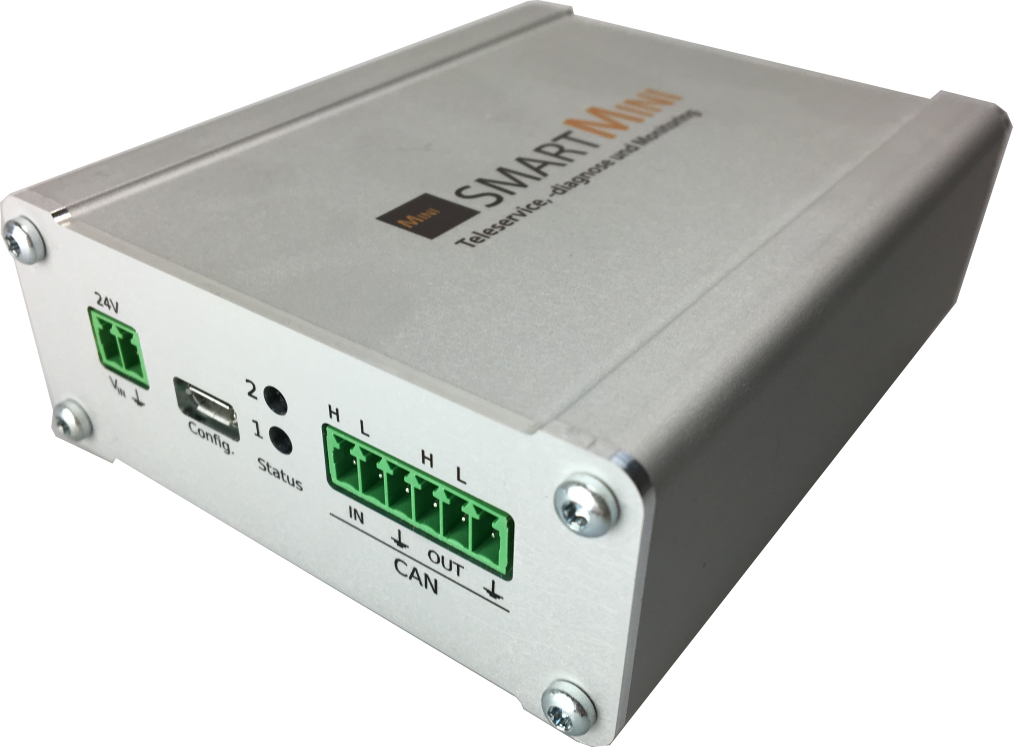
Power supply socket, micro USB for configuration, status LEDs and CAN bus](media/smartIO_can.png) Power supply socket, micro USB for configuration, status LEDs and CAN bus
Each module is individually tested for dielectric strength and insulation. With the robust aluminum housing and nano-coating of the circuit board, the requirements for requirements for use on rail vehicles are also met.
Power supply and CAN bus
The power supply and communication line to the higher-level device of the smart family (smartMINI, smartRAIL, etc.) are realized in the basic version with Phoenix terminals with a 3.5 mm pitch. CAN and power supply are isolated from the measuring voltages isolated from the measuring voltages. The CAN bus is looped through the device so that simple cascading is also possible with the cascading of several measuring modules is also possible with the terminals. The measuring module is equipped with reverse polarity protection.
In the smartRAIL version, power supply and CAN are available on two M12 connectors according to the Device-Net assignment. The power supply of 24V is looped through from the plug to the socket, as is the CAN bus connection. So several different smartIO modules can be connected in series.
If no further smartIO module follows, the CAN bus must be connected to a connector with an integrated terminating resistor (120 Ohm) or directly at the Phoenix terminal. terminal. CAN-GND is identical to the supply ground.
M12 connector of the smartRAIL system](media/deviceNet_M12.png) *M12 connector of the smartRAIL system
| Pin | Signal | Description |
|---|---|---|
| 1 | CAN-Shield | |
| 2 | +24V | Power supply +24V |
| 3 | GND | Reference ground for power supply and CAN bus |
| 4 | CAN_H | CAN bus: CAN-High |
| 5 | CAN_L | CAN bus: CAN-LOW |
Commercially available Device-Net cables can be used, which lead from socket to plug. plug can be used. For pre-assembled cables, twisted pair cable bundles must be selected for connection pairs 2 and 3 and 4 and 5, twisted pair cable bundles must be selected. For the inputs, Phoenix terminals with a 3.5 mm pitch are normally used, unless otherwise specified. terminals with a 3.5 mm pitch are normally used for the measurement inputs. The coding of the connectors makes it possible to pre-assembly of the connectors and a mix-up-proof connection is possible.